Appendix F: EIU supported configurations 169
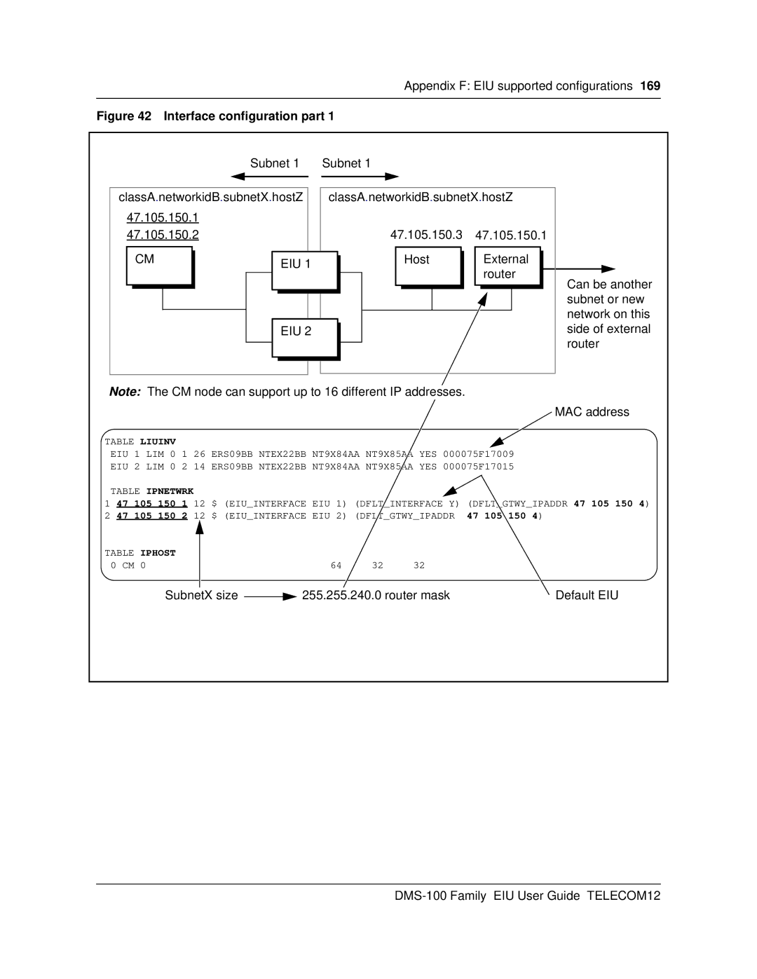
Figure 42 Interface configuration part 1
Subnet 1 | Subnet 1 | |
|
|
|
classA.networkidB.subnetX.hostZ | classA.networkidB.subnetX.hostZ | ||
47.105.150.1 |
|
|
|
47.105.150.2 |
| 47.105.150.3 | 47.105.150.1 |
CM | EIU 1 | Host | External |
|
| router | |
|
|
| |
|
|
| Can be another |
|
|
| subnet or new |
|
|
| network on this |
| EIU 2 |
| side of external |
|
|
| router |
Note: The CM node can support up to 16 different IP addresses.
MAC address
TABLE LIUINV
EIU 1 LIM 0 1 26 ERS09BB NTEX22BB NT9X84AA NT9X85AA YES 000075F17009
EIU 2 LIM 0 2 14 ERS09BB NTEX22BB NT9X84AA NT9X85AA YES 000075F17015
TABLE IPNETWRK
1 47 105 150 1 12 $ (EIU_INTERFACE EIU 1) (DFLT_INTERFACE Y) (DFLT_GTWY_IPADDR 47 105 150 4) 2 47 105 150 2 12 $ (EIU_INTERFACE EIU 2) (DFLT_GTWY_IPADDR 47 105 150 4)
TABLE IPHOST 0 CM 0
64 32 32
SubnetX size |
| 255.255.240.0 router mask | Default EIU |
|