Appendix H: ASU background information 181
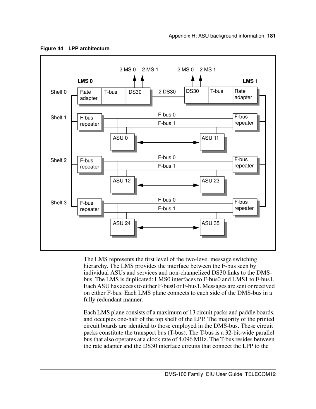
Figure 44 LPP architecture
|
|
| 2 MS 0 | 2 MS 1 | 2 MS 0 | 2 MS 1 |
|
| LMS 0 |
|
|
|
|
| LMS 1 |
Shelf 0 | Rate | DS30 | 2 DS30 | DS30 | Rate | ||
| adapter |
|
|
|
|
| adapter |
Shelf 1 |
|
|
|
| |||
|
|
|
|
| |||
| repeater |
|
|
|
| repeater | |
|
| ASU 0 |
|
| ASU 11 |
| |
Shelf 2 |
|
|
|
| |||
|
|
|
|
| |||
| repeater |
|
|
|
| repeater | |
|
| ASU 12 |
|
| ASU 23 |
| |
Shelf 3 |
|
|
|
| |||
|
|
|
|
| |||
| repeater |
|
|
|
| repeater | |
|
| ASU 24 |
|
| ASU 35 |
| |
The LMS represents the first level of the
Each LMS plane consists of a maximum of 13 circuit packs and paddle boards, and occupies