40Chapter 1: Introduction to the EIU
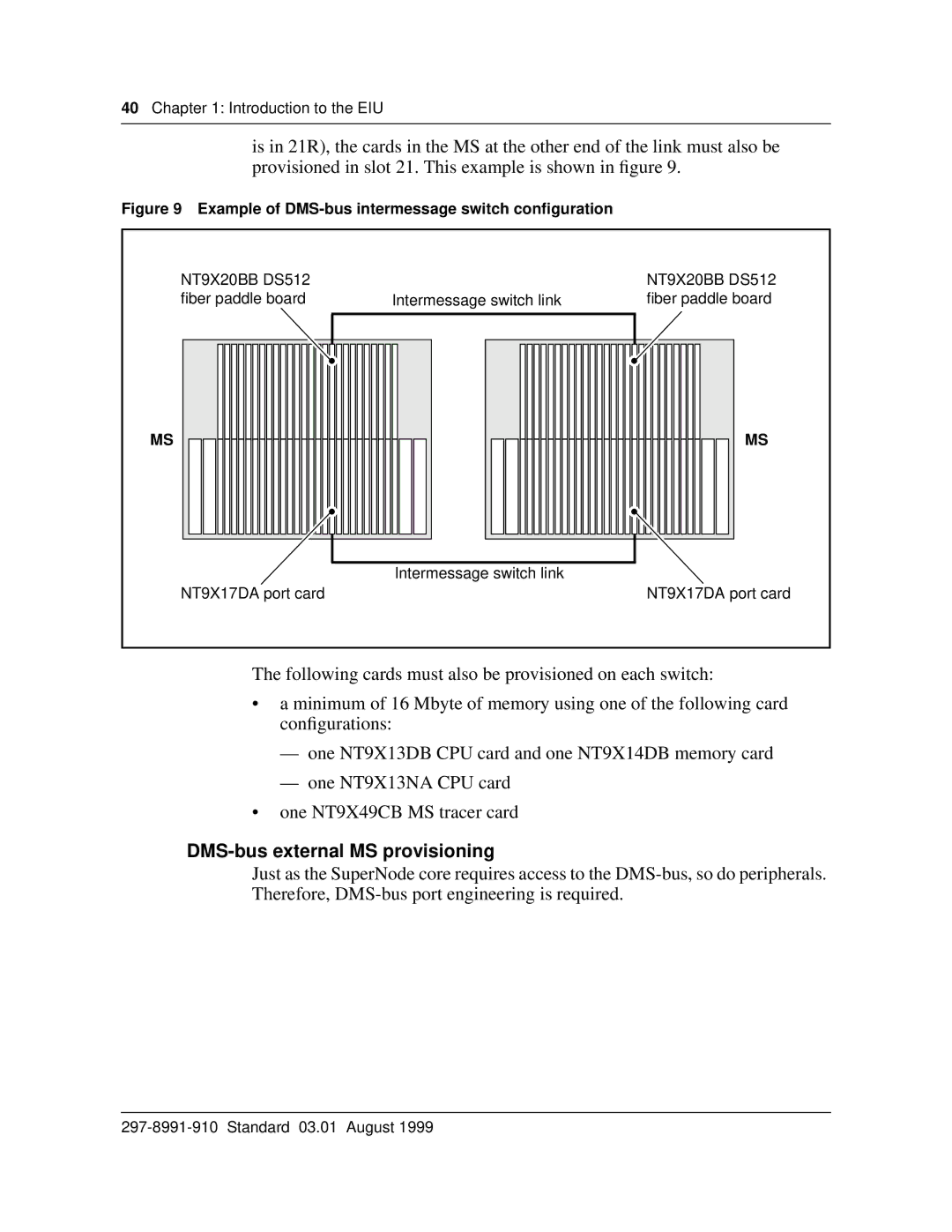
is in 21R), the cards in the MS at the other end of the link must also be provisioned in slot 21. This example is shown in figure 9.
Figure 9 Example of DMS-bus intermessage switch configuration
NT9X20BB DS512 |
| NT9X20BB DS512 |
fiber paddle board | Intermessage switch link | fiber paddle board |
MS |
| MS |
| Intermessage switch link |
|
NT9X17DA port card |
| NT9X17DA port card |
The following cards must also be provisioned on each switch:
•a minimum of 16 Mbyte of memory using one of the following card configurations:
—one NT9X13DB CPU card and one NT9X14DB memory card
—one NT9X13NA CPU card
•one NT9X49CB MS tracer card
DMS-bus external MS provisioning
Just as the SuperNode core requires access to the