Revision Firmware Version
External RAID Controller & Subsystem
Disclaimer
Copyright This Edition First Published
Iii
RMA Policy
Supported Models
Table of Contents
LCD Keypad Operation
LCD Screen Messages
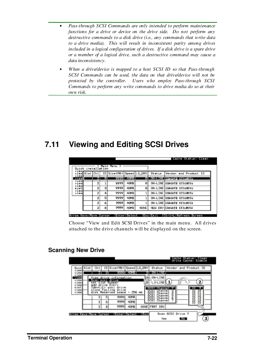
Viewing and Editing Scsi Drives
Viewing and Editing Logical Drives and Drive Members
Terminal Screen Messages
Terminal Operation
Vii
Viii
Fibre Operation
Advanced Configuration
Multi-Host Access Control LUN Filtering
Host-side and Drive-side Scsi Parameters
10-1
Redundant Controller
10-14
10-19
Array Expansion
Record of Settings
Appendix C System Functions Upgrading Firmware
Appendix D Event Messages
Xii
Functional Table of Contents
7.8
Xiv
Chapter Fibre Operation
Chapter Advanced Configurations
Chapter Redundant Controller Configuration
Chapter Array Expansion
Xvi
Xvii
Appendix C Controller Maintenance
Chapter
Xviii
Xix
Optimization Setting
About This Manual
Xxi
Revision History
Xxii
What is a logical volume?
Logical Volume
Logical Drive
Chapter
What are the RAID levels?
RAID Levels
RAID Levels
Infortrend
LogicalDrive
RAID 0+1
RAID 0+1
Disk Striping with Dedicated Parity Disk
Global and Local Spare Drives
Spare Drives
Local
Spare
12 Mixing Local and Global Spares
Flash Selected Scsi Drive
Identifying Drives
Flash All Scsi Drives
Flash All but Selected Drives
Automatic Rebuild and Manual Rebuild
Rebuild
14 Manual Rebuild
Manual Rebuild
Concurrent Rebuild in RAID 0+1
15 Logical Volume
Logical Volume Multi-Level RAID
16 Logical Drive Composed of 24 Drives
18 Logical Volume with Drives on Different Channels
Spare drives assigned to a logical volume?
Limitations
Different write policies within a logical volume?
RAID expansion with logical volume?
Different controller settings using logical volume?
Multi-level RAID systems
Logical volume with logical drives of different levels?
How many physical drives do you have?
How many drives on each drive channel?
RAID Planning
What kind of host application?
Dual loop, hub, or switch?
What RAID level?
Optimization Mode
Limitations?
Any spare drives?
Starting a RAID System
Array Configuration Process
Infortrend
Grouping Drives into an Array
1 I/O Channel, Scsi ID, and LUN
Physical locations of drive members
Mapping Partitions to Host ID/LUNs
Making Arrays Available to Hosts
Tunable Parameters
Controller Parameter Settings
Optimization Mode
Array Configuration
Following are guidelines on using the serial port
RS-232C Serial Port
Out-of-Band via Serial Port and Ethernet
Configuring RS-232C Connection via Front Panel
Keys used when operating via the terminal are as follows
Connecting Terminal
Starting RS-232C Terminal Emulation
Out-of-Band via Ethernet
What Is the Disk Reserved Space?
Connecting Ethernet Port
Other Concerns
Requirements
Use a Terminal Emulator to Begin Configuration
Configuring the Controller
Assign an IP Address to Ethernet Port
Starting the Manager
Snmptrap
NPC Onboard
Snmptrap section
Quick Installation Screen
Initial Screen
LCD Screen Messages
Logical Drive
Logical Drive Status
RAID level
Drive numbers
Logical Volume Status
Logical Volume Status
Scsi Drive Status
Default Scsi Bus Sync Clock
Channel Mode
Scsi Channel Status
Primary Controller Scsi ID Mapping
Controller Voltage and Temperature
Cache Dirty Percentage
UPS Power Failure Detected Press 2 Seconds to Clear Events
View and Edit Event Logs
View and Edit Event Logs
Caching Parameters
Power on RAID Enclosure
Optimization Modes
Front Panel Operation
Database and Transaction-based Applications
Optimization Mode and Stripe Size
Write-Back/Write-Through Cache Enable/Disable
Write-Back Cache Enabled Disable Write
Optimization for Random or Sequential I/O
Infortrend
View and Edit Scsi Drives
View Connected Drives
=2 I=0 1010MB New DRV Seagate
View Drive Information
Choosing a RAID Level
Creating a Logical Drive
Choosing Member Drives
Logical Drive Preferences
Maximum Drive Capacity
Initialization Mode
Spare Drive Assignments
Disk Reserved Space
On-Line Mode
Stripe size Default ?
Stripe Size
Beginning Initialization
Off-Line Mode
Creating a Logical Volume
Logical Volume Assignment
Partitioning a Logical Drive/Logical Volume
View Edit Host Luns
Mapping a Logical Volume/Logical Drive to Host LUN
Adding a Local Spare Drive
Assigning Spare Drive and Rebuild Settings
MAP to LV=0 PRT=0?
View and Edit Scsi Drives =2 I=4 1010MB
Rebuild Settings
Adding a Global Spare Drive
Add Global Spare Drive Add Global Spare Drive Successful
Deleting a Logical Drive
Viewing and Editing Logical Drives and Drive Members
Drive Space Allocated to the Last Partition
Deleting a Partition of a Logical Drive
Rebuilding a Logical Drive
Assigning a Name to a Logical Drive
View and Edit Logical Drives LG0 RAID5 DRV=3 2012MB FL SB=0
Rebuild Logical Drive Drive? Rebuilding 25% Please Wait
LG0 RAID5 DRV=3 2012MB RB SB=0 Rebuild Progress
Regenerating Logical Drive Parity
View and Edit Logical Drives LG0 RAID5 DRV=3 4095MB GD SB=0
Media Scan
Write Policy
Pass-through Scsi Commands
Viewing and Editing Host LUNs
Viewing and Deleting LUN Mappings
Viewing and Editing Scsi Drives
Scanning New Scsi Drive
Scan Channel=1 ID=1 Scan Fail
=1 I=1 Absent
Identifying a Drive
Redefining Channel Mode
Viewing and Editing Scsi Channels
Deleting Spare Drive Global / Local Spare Drive
Adding a Channel ID
Setting a Scsi Channel’s ID Host Channel Viewing IDs
Add Channel
Primary Controller ? Add CHL=0 ID=2 Primary Ctlr ?
Deleting a Channel ID
Setting a Scsi Channel’s Primary ID Drive Channel
Delete Channel
Delete ID=2 Primary Ctlr ?
Setting Channel Bus Terminator
Setting a Scsi Channel’s Secondary ID Drive Channel
Scsi Terminator Enabled CHL=0 Disable Terminator ?
Setting Transfer Speed
Viewing and Editing Scsi Target Drive Channel
Setting Transfer Width
View and Edit Scsi Channels CH1=Drive PID=7
View and Edit Scsi Target
Slot Number
Maximum Synchronous Transfer Clock
Maximum Transfer Width
Parity Check
Disconnecting Support
Maximum Tag Count
Max Xfer Narrow Only?
Restore to Default Setting
Changing Password
Change Password
System Functions
Mute Beeper
Disabling Password
Reset Controller
Shutdown Controller
ShutdownComplete Reset Ctlr?
Restore Nvram from Disks
Controller Maintenance Save Nvram To Disks
Restore Nvram From Disks
Controller Parameters
Password Validation Timeout
Controller Name
LCD Title Display Controller Name
Controller Date and Time
Time Zone
Time Zone
Date and Time
GMT +0800
Date and Time MMDDhhmmYYYY
Scsi Drive Low-level Format
Scsi Drive Utilities
View and Edit Scsi Drives =1 I=1 8683MB
Scsi Drives Utilities Drive Read/Write Test
Scsi Drive Read/Write Test
PC Graphic Ansi Mode
Transfer Rate Indicator
Terminal VT-100 Mode
Cursor Bar
Main Menu
Quick Installation
Terminal Screen Messages
Status
SizeMB
Name
Column C
Chl
Slot
Size MB
Speed
PID
Scsi Channel’s Status
Term
CurSynClk
CurWid
Controller voltage and temperature monitoring
Viewing Event Logs on the Screen
Terminal Operation
Terminal Operation
Limitations
Optimization Mode and Stripe Size
Viewing the Connected Drives
Creating a Logical Drive
Choosing a RAID Level
Logical Drive Assignments
Assign Spare Drives
Initialization Mode
Terminal Operation
Creating a Logical Volume
Partitioning a Logical Drive/Logical Volume
Infortrend
Mapping a Logical Volume to Host LUN
Infortrend
Adding Local Spare Drive
Assigning Spare Drive, Rebuild Settings
Viewing and Editing Logical Drive and Drive Members
1000MB
Rebuilding a Logical Drive
Applies to RAID1, 3,
Iteration Count
Edit Host-ID/WWN Name List
Viewing or Deleting LUN Mappings
Scanning New Drive
Identifying Drive
Slot Number Drive Entry
Terminal Operation
Viewing and Editing Scsi Channels
Viewing and Editing Scsi IDs Host Channel
Deleting an ID
Setting a Primary Controller’s Scsi ID Drive Channel
Setting Channel Terminator
Setting a Secondary Controller’s Scsi ID Drive Channel
Setting a Transfer Speed
Drive Channel
Host Channel
Setting the Transfer Width
Viewing and Editing Scsi Target / Drive Channel
Maximum Synchronous Transfer Clock
Data Rate
Infortrend
System Functions
Setting a New Password
Changing the Password
Disabling the Password
Controller Parameters
Saving Nvram to Disks
Password Validation Timeout
Terminal Operation
Set Controller Date and Time
Drive Information
Scsi Drive Utilities
View Drive Information
Scsi Drive Low-level Format
Scsi Drive Read/Write Test
Fibre Operation
Overview
Major Concerns
Fibre Operation
Supported Features
Fibre Chip
Multiple Target IDs
In-band Fibre and S.E.S. Support
Drive IDs
Configuration Host and Drive Parameters
Channel Mode
Primary and Secondary Controller IDs
Redundant Controller Cache Coherency Channel RCC Channel
View Channel WWN
Limitation
View Device Port Name List Wwpn
View and Edit Fibre Drive
User-Assigned ID Scan Scsi Drive
View and Edit Host-Side Parameters
View and Edit Drive-Side Parameters Drive-Side Dual Loop
Fibre Channel Connection Type
Controller Unique Identifier
Controller Communications over Fibre Loops
Fibre Operation
Storage Pool
Multi-Host Access Control LUN Filtering
Host-LUN Mapping
Creating LUN Masks
WWN Name List
Logical Unit to Host LUN Mapping
Infortrend
Filter Type Include or Exclude
LUN Mask ID Range Configuration
Access Mode Read Only or Read/Write
Sample Configuration
Configuration Procedure
Infortrend
Fault Prevention
Advanced Configurations
A.R.T
Replace after Clone
Clone Failing Drive
Perpetual Clone
Advanced Configurations
Introduction
Detect Only
Disable
Perpetual Clone
Clone + Replace
Configuration Procedure
Enabling the S.M.A.R.T. Feature
Examining Whether Your Drives Support S.M.A.R.T
Detect Only Setting
Using S.M.A.R.T. Functions
Detect, Perpetual Clone Setting
Detect, Clone+Replace Function
Host-side and Drive-side Scsi Parameters
Host-side Scsi Parameters
Foreword Scsi Channel, Scsi ID and LUN
Number of Tags Reserved for each Host-LUN Connection
Maximum Queued I/O Count
LUNs per Host Scsi ID
LUN Applicability
What is In-band?
Peripheral Device Type
In-band Scsi or Fibre
SCO
Peripheral Device Type Parameters
Device Type Setting
Peripheral Device Type Settings
Cylinder/Head/Sector Mapping
Cylinder/Head/Sector Mapping under Sun Solaris
Configuring Sector Ranges/Head Ranges/Cylinder Ranges
Scsi Motor Spin-Up
Drive-side Parameters
Scsi Reset at Power-Up
Scsi I/O Timeout
Disk Access Delay Time
Maximum Tag Count Tag Command Queuing
Detection of Drive Hot Swap Followed by Auto Rebuild
SAF-TE and S.E.S. Enclosure Monitoring
Periodic Drive Check Time
Periodic Auto-Detect Failure Drive Swap Check Time
Idle Drive Failure Detection
Advanced Configurations
Monitoring and Safety Mechanisms
Dynamic Switch Write-Policy
View Peripheral Device Status
Controller Auto-Shutdown Event Trigger Option
Rebuild Priority
Disk Array Parameters
Verification on Writes
Redundant Controller 10-1
Operation Theory
Considerations Related to Physical Connection
Setup Flowchart
SCSI-Based Controllers
10-2 Infortrend
Redundant Controller 10-3
Fibre-Based Controllers
10-4 Infortrend
Grouping Hard Drives and LUN Mapping
Redundant Controller 10-5
Logical Drive, Logical Volume, and Logical Partitions
System Drive Mapping
Primary and Secondary IDs
10-6 Infortrend
Redundant Controller 10-7
Mapping
Fault-Tolerance
What Is a Redundant Controller Configuration?
10-8 Infortrend
Redundant Controller 10-9
How does Failover and Failback Work? Channel Bus
ID Mapping Status Normal Operation
ID Mapping Status Controller Failed
10-10 Infortrend
Controller Failover and Failback
Active-to-Active Configuration
Replacing a Failed Unit
Auto-Failback
Redundant Controller 10-12
Traffic Distribution and Failover Process
Controller Failure
Symptoms
Connection
10-13 Infortrend
Requirements
Preparing Controllers
Cabling Requirements
Controller RCC cable
Redundant Controller 10-15
Controller Settings
Limitations
Configurable Parameters
Primary or Secondary
10-16 Infortrend
Battery Support
Active-to-Standby Configuration
Cache Synchronization
Redundant Controller 10-17
10-18 Infortrend
Redundant Controller 10-19
Configuration
Enable Redundant Controller
Redundant Configuration Using Automatic Setting
Autoconfig
Via Front Panel Keypad
Redundant Configuration Using Manual Setting
View and Edit Peripheral Dev
Redundant Controller 10-21
Starting the Redundant Controllers
RC connecting ENT to cancel
Creating Primary and Secondary ID
10-22 Infortrend
CHL=0 ID=0 Primary Ctlr Add Channel
Set Sec. Ctlr Idna to ID 6?
View and Edit Logical Drives
Redundant Controller 10-23
10-24 Infortrend
Mapping a Logical Drive/Logical Volume to the Host LUNs
When and how is the failed controller replaced?
What will happen when one of the controllers fails?
Front Panel View of Controller Failure
Redundant Ctlr Failure Detected
10-26 Infortrend
Via Terminal Emulation
Redundant Controller 10-27
10-28 Infortrend
Redundant Controller 10-29
Assigning Logical Drives to the Secondary Controller
10-30 Infortrend
When and How Is the Failed Controller Replaced?
Terminal Interface View of Controller Failure
Redundant Controller 10-31
10-32 Infortrend
Redundant Controller 10-33
Forcing Controller Failover for Testing
Secondary Controller RS-232
RCC Status Redundant Controller Communications Channel
Remote Redundant Controller
Cache Synchronization on Write-Through
View and Edit Logical Drives
Record of Settings 11-1
11-2 Infortrend
Record of Settings 11-3
View and Edit Logical Volumes
11-4 Infortrend
View and Edit Host LUN’s
Record of Settings 11-5
11-6 Infortrend
View and Edit Scsi Drives
View and Edit Scsi Channels
Record of Settings 11-7
View and Edit Configuration Parameters
Communication Parameters
11-8 Infortrend
Host Side Scsi Parameters
Record of Settings 11-9
11-10 Infortrend
Disk Array Parameters
View and Edit Peripheral Devices
Record of Settings 11-11
Save Nvram to Disk, Restore from Disk
RAID Security Password
11-12 Infortrend
Array Expansion
What is it and how does it work?
Added Capacity
Array Expansion
Expand Logical Drive Re-Striping
Add-Drive Procedure
Mode 1 Expansion Adding Drives to a Logical Drive
12-5
12-6
Expansion by Copy & Replace
Copy and Replace Procedure
12-8
12-9
Making Use of the Added Capacity Expand Logical Drive
12-10
Expand Logical Volume
Example
Limitations When Using Windows
12-13
12-14
12-15
12-16
12-17
Start
Navigation Map
Create
View and Edit Scsi Drives
View and Edit Scsi Channels
View and Edit Configuration Parameters
View and Edit Peripheral Device
End
Appendix
Basic RAID Management
Advanced Features
128
Caching Operation
Caching Optimization
RAID Expansion
Fibre Channel Support
Redundant Controller
A.R.T. Support
Data Safety
System Security
Environment Management
Remote Manageability
User Interface
Others
JBOD-Specific
Redundant Controller Rolling Firmware Upgrade
Upgrading Firmware
System Functions Upgrading Firmware
Establish the In-band Scsi connection in RAIDWatch Manager
Redundant Controller Firmware Sync-version
Upgrade Both Boot Record and Firmware Binaries
Upgrade the Firmware Binary Only
Upgrading Firmware Using RS-232C Terminal Emulation
Upgrading Both Boot Record and Firmware Binaries
Upgrading the Firmware Binary Only
Event Index
Controller Event
Event Messages
Notification
Drive Scsi Channel/Drive Error
General Target Events
Logical Drive Event
I2C Device
Notification SAF-TE Device
3fa2 Notice Controller FAN Back On-Line RPM
Happens?
Controller Event
Happens? What to Do?
Happens? What to Do?
Drive Scsi Channel/Drive Error
Received Sensekey Sensecode
Happens? What to Do? Line LCD
= I= Unexpected Sense Rec
What to Do?
What to Press ESC to clear the message
Red Path for C Failure Detected
Logical Drive Event
Infortrend
Happens?
Infortrend
Event Type
General Target Events
Controller On-board
Event Type
Check I 2C cable connection and contact your system supplier
3F22 Peripheral Device Alert high/low threshold Fan Speed
Event Messages
SES Device
Line LCD . Temp Sensor Device Unknown Status
What Happens? What to
Line LCD . Current Sensor Device Not Supported
Infortrend
What Happens?
Temperature back to non-critical level
Controller Self Diagnostics
Contlr FAN Back On-Line
Happens?
SES Device Alert
Alert Notification What UPS device failure detected
Index-1
Index
Index-2 Infortrend
Index-3
Index-4 Infortrend
Index-5
Nvram
Index-6 Infortrend
RCC
Index-7
Index-8 Infortrend
Zmodem