D-Link DHS-3224V manual Front Panel, Rear Panel

Models: DHS-3224V

1 162
Download 162 pages 31.12 Kb
Page 22
Image 22

D-Link DHS-3224V Switch User’s Guide

3

Switch Components

This chapter describes the front panel, rear panel, side panels, optional plug-in modules, and LED indicators of the DHS-3224V.

Front Panel

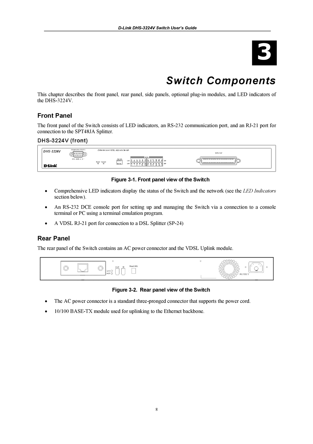
The front panel of the Switch consists of LED indicators, an RS-232 communication port, and an RJ-21 port for connection to the SPT48JA Splitter.

Figure 3-1. Front panel view of the Switch

Comprehensive LED indicators display the status of the Switch and the network (see the LED Indicators section below).

An RS-232 DCE console port for setting up and managing the Switch via a connection to a console terminal or PC using a terminal emulation program.

A VDSL RJ-21 port for connection to a DSL Splitter (SP-24)

Rear Panel

The rear panel of the Switch contains an AC power connector and the VDSL Uplink module.

Figure 3-2. Rear panel view of the Switch

The AC power connector is a standard three-pronged connector that supports the power cord.

10/100 BASE-TX module used for uplinking to the Ethernet backbone.

8

Page 22
Image 22
D-Link DHS-3224V manual Front Panel, Rear Panel