D-Link DHS-3224V Switch User’s Guide

Front Panel Connections

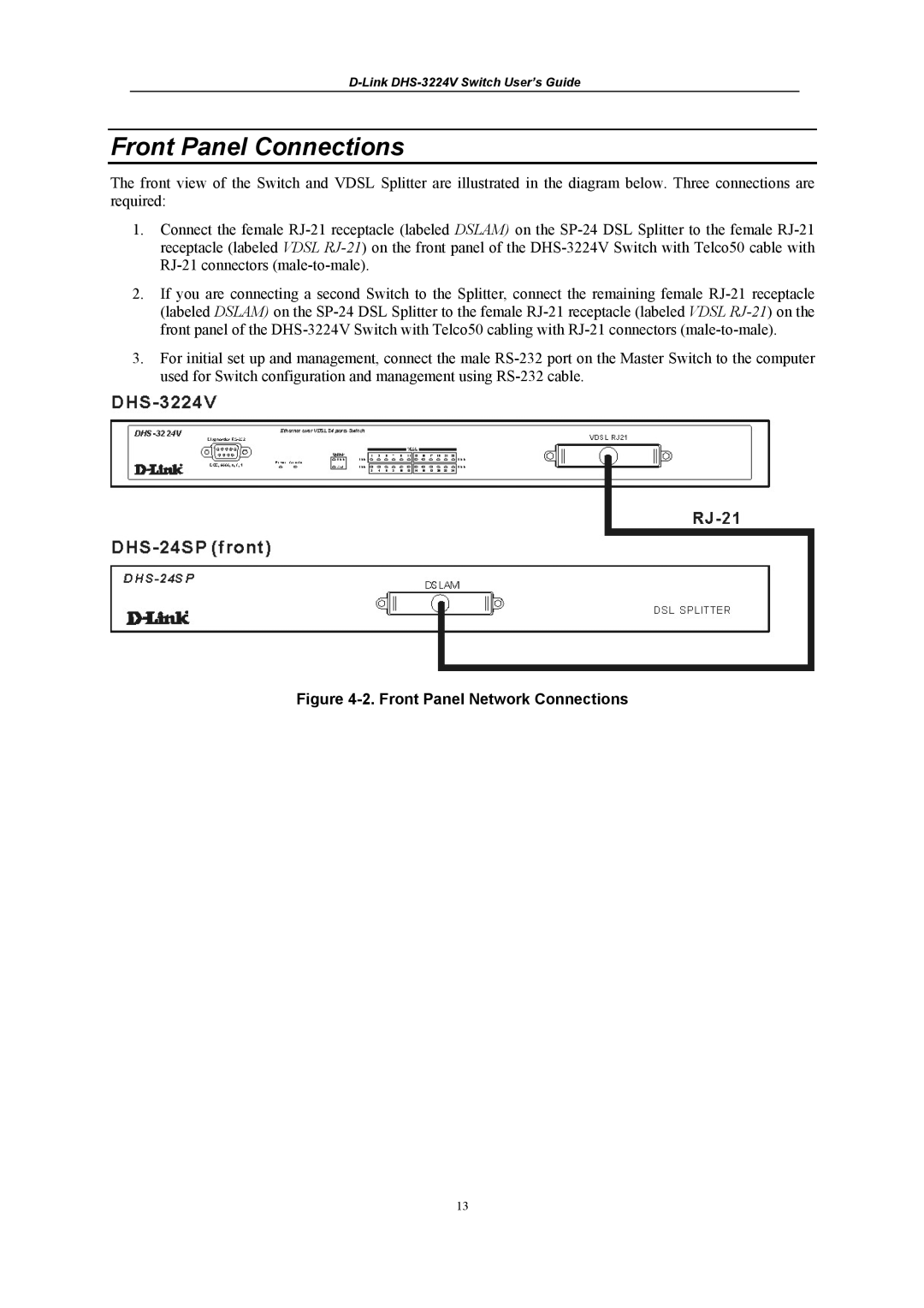
The front view of the Switch and VDSL Splitter are illustrated in the diagram below. Three connections are required:

1.Connect the female RJ-21 receptacle (labeled DSLAM) on the SP-24 DSL Splitter to the female RJ-21 receptacle (labeled VDSL RJ-21) on the front panel of the DHS-3224V Switch with Telco50 cable with RJ-21 connectors (male-to-male).

2.If you are connecting a second Switch to the Splitter, connect the remaining female RJ-21 receptacle (labeled DSLAM) on the SP-24 DSL Splitter to the female RJ-21 receptacle (labeled VDSL RJ-21) on the front panel of the DHS-3224V Switch with Telco50 cabling with RJ-21 connectors (male-to-male).

3.For initial set up and management, connect the male RS-232 port on the Master Switch to the computer used for Switch configuration and management using RS-232 cable.

Figure 4-2. Front Panel Network Connections

13

Page 27
Image 27
D-Link DHS-3224V manual Front Panel Connections, Front Panel Network Connections