Illustration of STP
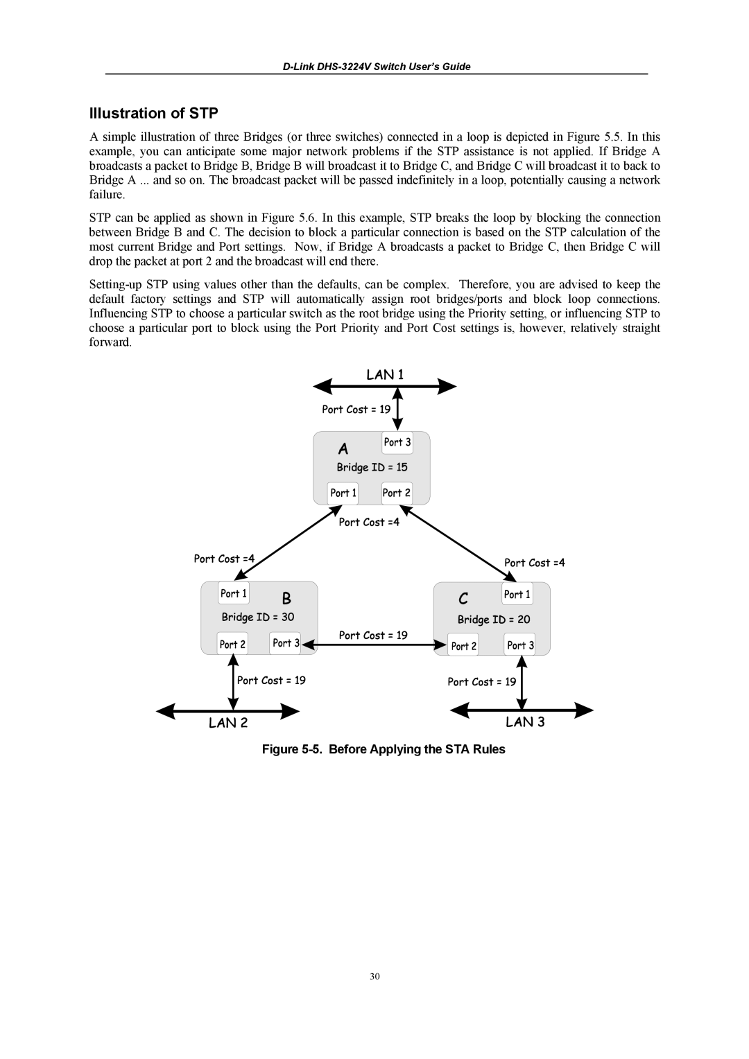
A simple illustration of three Bridges (or three switches) connected in a loop is depicted in Figure 5.5. In this example, you can anticipate some major network problems if the STP assistance is not applied. If Bridge A broadcasts a packet to Bridge B, Bridge B will broadcast it to Bridge C, and Bridge C will broadcast it to back to Bridge A ... and so on. The broadcast packet will be passed indefinitely in a loop, potentially causing a network failure.
STP can be applied as shown in Figure 5.6. In this example, STP breaks the loop by blocking the connection between Bridge B and C. The decision to block a particular connection is based on the STP calculation of the most current Bridge and Port settings. Now, if Bridge A broadcasts a packet to Bridge C, then Bridge C will drop the packet at port 2 and the broadcast will end there.
Figure 5-5. Before Applying the STA Rules
30