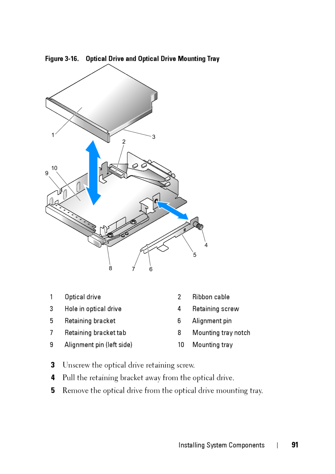
Figure 3-16. Optical Drive and Optical Drive Mounting Tray
1 | 2 | 3 |
| ||
|
|
9 10
|
|
|
| 4 |
|
|
|
| 5 |
| 8 | 7 | 6 |
|
1 | Optical drive |
| 2 | Ribbon cable |
3 | Hole in optical drive |
| 4 | Retaining screw |
5 | Retaining bracket |
| 6 | Alignment pin |
7 | Retaining bracket tab |
| 8 | Mounting tray notch |
9 | Alignment pin (left side) | 10 | Mounting tray | |
3Unscrew the optical drive retaining screw.
4Pull the retaining bracket away from the optical drive.
5Remove the optical drive from the optical drive mounting tray.
Installing System Components
91
