Manuals
/
Dell
/
Computer Equipment
/
Laptop
Dell
R900
manual
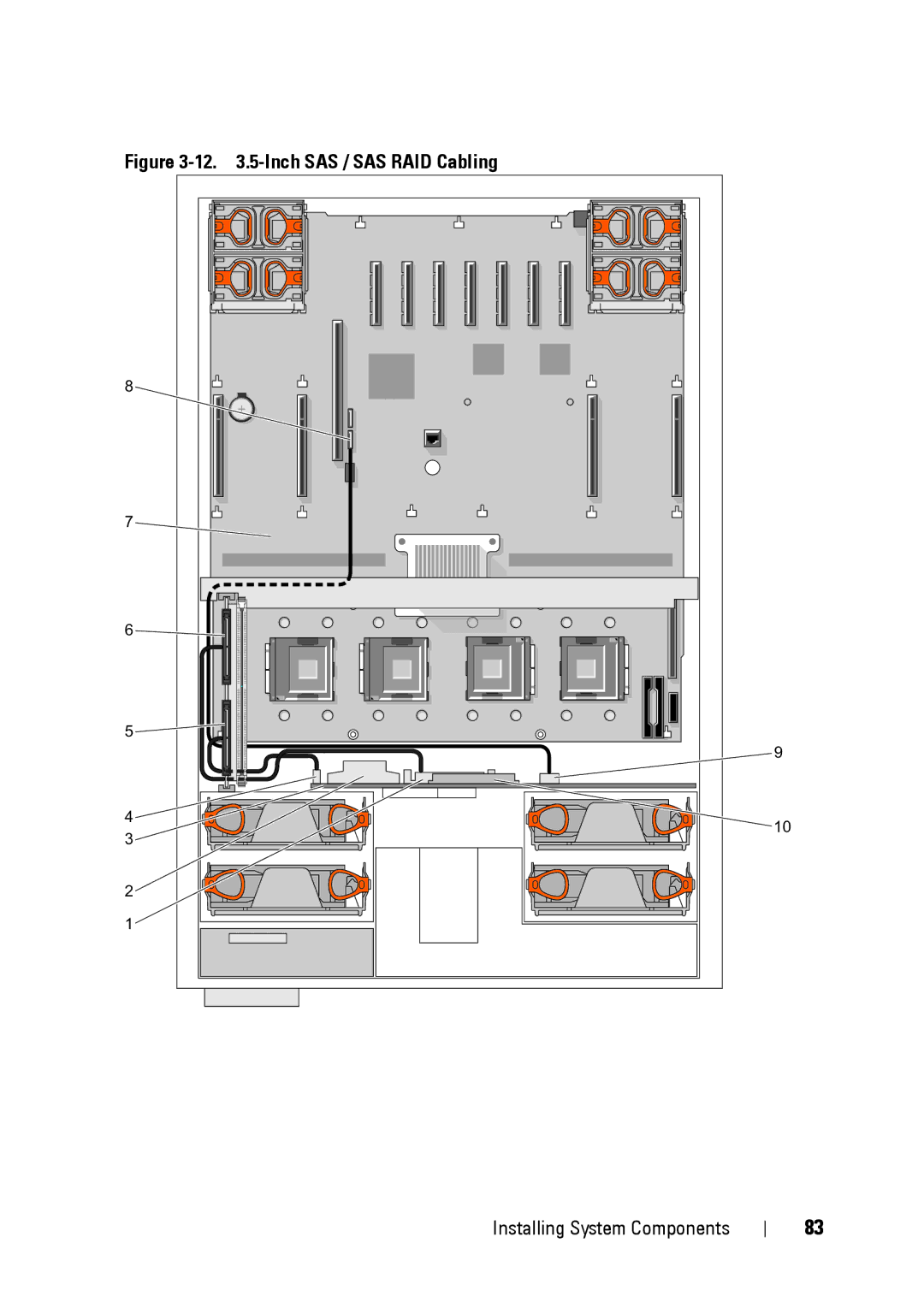
12 .5-Inch SAS / SAS RAID Cabling
Models:
R900
1
83
190
190
Download
190 pages
58.51 Kb
80
81
82
83
84
85
86
87
Troubleshooting
Install
Error codes
Password
Hard Drive Indicator Codes
Connecting External Devices
E2020 CPU Config
Problem
Diagnostics Messages
Using the System Setup Program
Page 83
Image 83
Figure
3-12.
3.5-Inch
SAS / SAS RAID Cabling
8
7
6
5
9
4
10
3
2
1
Installing System Components
83
Page 82
Page 84
Page 83
Image 83
Page 82
Page 84
Contents
Page
September XK946
Contents
Removing and Installing the Top Cover
Disabling a Forgotten Password
Replacing a Hard Drive Carrier
101
Troubleshooting External Connections
Replacing the System Battery
Safety First-For You and Your System
Troubleshooting IRQ Assignment Conflicts
133
Troubleshooting a Wet System 134
Using PowerEdge Diagnostics 149 System Diagnostics Features
Executing System Diagnostics 150
153
Glossary
Other Information You May Need
About Your System
Keystrokes for Accessing System Functions Description
Accessing System Features During Startup
Front Panel Features and Indicators
Before the power is turned off. If
Hard Drive Indicator Codes
Hard Drive Indicators
Smart
Hard Drive Indicators Pattern Green element Amber eLement
Connecting External Devices
Back Panel Features and Indicators
Power Indicator Codes
Indicator Function
Redundant Power Supply Indicators
LCD Status Messages
Indicators Illumination Meaning
NIC Indications
System Name
LCD Status Messages Code Test Causes
LCD Status Messages Code Test Causes Corrective Actions
E1210 Cmos Batt
E1418 CPU #
E141F CPU
PCI Perr
E1712 PCI Serr
CPU
DMA
E2020 CPU Config
E2112 Mem Spare Crd # Dimm
Removing LCD Status Messages
Solving Problems Described by LCD Status Messages
System Messages Corrective Action
System Messages
System Messages
Remote Access Controller initialization
Defective system board
Expansion card improperly installed or
Alert Messages
Diagnostics Messages
About Your System
Responding to Error Messages
Entering the System Setup Program
Setup Menu Key Use Function Description
Using the System Setup Program
Main Screen
System Setup Options
System Setup Program Options Description
CPU Information Screen Option Description
Memory Information Screen
CPU Information Screen
Memory Information Screen Option Description
Integrated Devices Screen Options Description
Integrated Devices Screen
Serial Communication Screen Options Description
PCI IRQ Screen
Serial Communication Screen
PCI IRQ Screen Options Description
System Security Screen Options Description
Embedded Server Management Screen
System Security Screen
Embedded Server Management Options Description
10. TPM Security Screen Options Description
System and Setup Password Features
Trusted Platform Module TPM Security Screen
Exit Screen
Assigning a System Password
Using the System Password
Using Your System Password to Secure Your System
Changing the System Password
Disabling an Existing System Password
Assigning a Setup Password
Using the Setup Password
Disabling the System Password
Disabling a Forgotten Password
Baseboard Management Controller Configuration
Operating With a Setup Password Enabled
BMC Setup Module Options
Entering the BMC Setup Module
Using the System Setup Program
Installing System Components
Inside the System
Recommended Tools
Inside the System
Removing and Installing the Top Cover
Removing the Top Cover
Installing the Top Cover
Removing the Top Cover
Removing a Drive Blank
Hard Drives
Before You Begin
Removing a Drive Blank
Installing a Drive Blank
Removing a Hot-Plug Hard Drive
Removing a Hot-Plug Hard Drive
Installing a Hot-Plug Hard Drive
Removing a Hard Drive From a Hard Drive Carrier
Installing a SAS Hard Drive Into a SATAu Drive Carrier
Replacing a Hard Drive Carrier
SATAu SAS
Removing a Power Supply
Power Supplies
Removing a Power Supply
Installing a Power Supply
Removing a Front System Fan
Installing a Front System Fan
System Fans
Hot-plugging a Front System Fan
Hot-plugging a Front System Fan
Removing a Back System Fan
Hot-plugging a Back System Fan
Installing a Back System Fan
Removing a Back System Fan Housing
Removing a Back System Fan Housing
Installing a Back System Fan Housing
Removing the Cooling Shroud
Cooling Shroud
Removing the Cooling Shroud
Installing the Cooling Shroud
SAS Controller Card
10. SAS RAID Controller Card
SAS and SAS RAID Controller Card Cabling Guidelines
Installing an SAS Controller Card
Removing a SAS Controller Card
11 .5-Inch SAS / SAS RAID Cabling
Sataa connector on system board
12 .5-Inch SAS / SAS RAID Cabling
Installing a RAID Battery
RAID Battery
13. Installing a RAID Battery
Removing a RAID Battery
PCI Express Add-in Cards
Configuring the Boot Device
Installing a PCI Express Card
14. Installing and Removing PCI Express Cards
Removing the Optical Drive
Optical Drive
Removing a PCI Express Card
15. Removing the Optical Drive
Installing the Optical Drive
Replacing an Optical Drive Mounting Tray
16. Optical Drive and Optical Drive Mounting Tray
System Memory
General Memory Module Installation Guidelines
Memory Sparing Support
Non-Optimal Memory Configurations
Riser a Riser B Riser C Riser D Memory Modes
Valid Memory Configurations Branch
Memory Mirroring Support
Channel
Dimm A1 Dimm B1 Dimm C1 Dimm D1
Removing a Memory Riser
17. Removing a Memory Riser
Memory Population Rules
Installing a Memory Riser
Removing the Memory Riser Cover
Installing Memory Modules
100
18. Installing Memory Modules
101
Processors
Removing Memory Modules
Removing a Processor Heat Sink
102
103
19. Installing and Removing a Processor Heat Sink
104
Installing a Processor Heat Sink
Removing a Processor
105
Installing a Processor
21. Removing a Processor Filler Blank
106
107
108
System Battery
Replacing the System Battery
109
22. Replacing the System Battery
110
Activating the NIC TOE
Riser
Removing the I/O Riser
111
Installing the I/O Riser
112
Installing a Drac
113
24. Installing a Drac
114
SAS Backplane Service-only Procedure
Removing the SAS Backplane 3.5 Hard Drives
25. Removing the SAS Backplane 3.5-inch Hard Drives
115
116
Installing the SAS Backplane 3.5-inch Hard Drives
Removing the SAS Backplane 2.5-inch Hard Drives
117
26. Removing the SAS Backplane 2.5-inch Hard Drives
118
119
Installing the SAS Backplane 2.5 Hard Drives
Removing the Power Interposer Board
120
27. Removing the Power Interposer Board
121
Installing the Power Interposer Board
122
System Board Service-only Procedure
Removing the System Board
123
124
Installing the System Board
125
126
Start-Up Routine Indications Look/listen for Action
Safety First-For You and Your System
Start-Up Routine
127
128
Troubleshooting IRQ Assignment Conflicts
IRQ Assignment Defaults IRQ Line
Checking the Equipment
Action
Troubleshooting External Connections
Troubleshooting the Video Subsystem
Problem
130
Troubleshooting the Keyboard
131
Troubleshooting Basic I/O Functions
Troubleshooting the Mouse
132
Troubleshooting a Serial I/O Device
Troubleshooting a USB Device
133
Troubleshooting a NIC
134
Troubleshooting a Wet System
135
Troubleshooting a Damaged System
136
Troubleshooting the System Battery
137
Troubleshooting Power Supplies
138
Troubleshooting System Cooling
Troubleshooting a Fan
139
Troubleshooting System Memory
140
141
Troubleshooting an Optical Drive
142
Troubleshooting a Hard Drive
143
144
Troubleshooting a SAS or SAS RAID Controller Card
145
Troubleshooting Expansion Cards
146
147
Troubleshooting Processors
148
149
Using PowerEdge Diagnostics
System Diagnostics Features
System Diagnostics Testing Options Function
When to Use the System Diagnostics
Executing System Diagnostics
System Diagnostics Testing Options
151
Using the Custom Test Options
Selecting Devices for Testing
Selecting Diagnostics Options
152
Viewing Information and Results
153
System Board Jumpers and Connectors
154
System Board Connectors
System Board Jumpers Location Setting Description
155
System Board Connectors Description
156
SAS Backplane Connectors
157
SAS Backplane Connectors 2.5-Inch System Front
158
SAS Backplane Connectors 2.5-Inch System Back
159
SAS Backplane Connectors 3.5-inch x5 Option Front
160
Power Interposer Connectors
161
Power Interposer Connectors 2.5-inch x8 Option Front
162
163
164
165
Obtaining Assistance
166
Online Services
167
Automated Order-Status Service
Support Service
168
Before You Call
169
Diagnostics Checklist
170
Contacting Dell
171
Glossary
172
173
174
175
176
177
178
179
180
181
182
183
Index
184
185
186
NIC
187
Post
188
Expansion card
189
190
Top
Page
Image
Contents