DVS 510 Series
Safety Instructions English
FCC Class a Notice
Variables are written in slanted form as shown here
Conventions Used in this Guide
Extron Electronics. All rights reserved
Contents
Creating Labels Using the Button Label Generator 113
102
104
107
About this Guide
About the DVS 510 Series Scalers
Features
DVS 510 Series Introduction
Controlling the DVS 510 Series
Rack-mountable 2U, full rack width metal enclosure
Application Diagram
Connection Diagram for a DVS 510 SA
Installation
Installation Overview
Rear Panel
Video inputs 5 and 6 buffered RGB or YUV component Connect
DVIIM-VGAF/DVIIF DVI and Analog Breakout Cable
Unbalanced Stereo Input
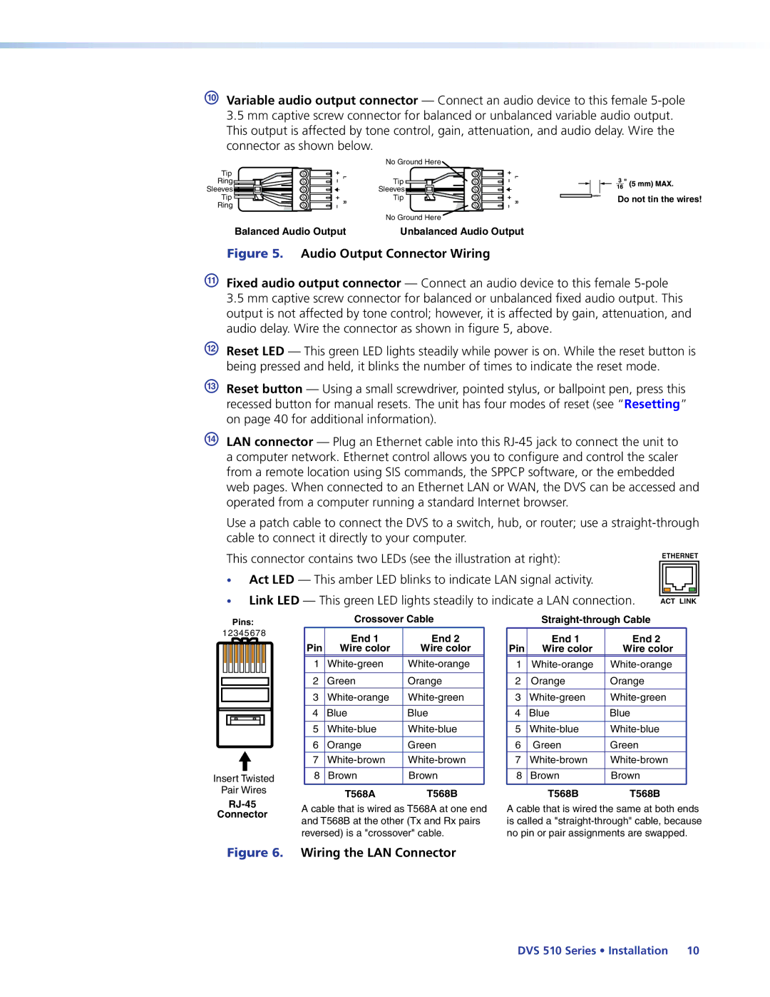
Audio Output Connector Wiring
Connecting to the RS-232 Config Port Front Panel
Pin Assignments for the RS-232 Port
Red Black Positive + Negative
Wiring the Amplified Audio Port DVS 510 SA Only
Speaker system. See on the next page for examples
Speaker Connection Examples
Front Panel
DVS 510 and DVS 510 SA Front Panel
2 Composite 4 S-video
10 DVI
DVS 510 Series Operation
Powering On
Power-up and Default Cycle
Picture-in-Picture PIP Mode
Audio and video breakaway are not allowed
Using the PIP Swap Feature
Enabling PIP Mode
Changing the PIP Input
Menus on the LCD Screen
Using the menus
Menu System Overview
Menu flow diagram
Cycle
User Presets Menu
Saving or recalling a user preset
Input Configuration Menu
Input
Composite
Video
Configuring an input
Available input adjustments
Input configuration submenu adjustments
Selecting an input
Film Mode Detect
Pixel Phase Inputs 5, 6, 7,
Vertical Start Position
Horizontal Start Position
Output Configuration Menu
Resolutions and refresh rates submenu
Output Type submenu
Sync Polarity submenu
Audio Configuration Menu
Gain/Attenuation submenu
Bass and Treble submenus
Limiter submenu DVS 510 SA only
Audio Delay submenu
Advanced Configuration Menu
Audio Output submenu
Auto Image submenu
Auto Memories submenu
Aspect Ratio submenu
RGB Delay submenu
Auto Memories and Auto-Image Interaction
Off default
Switch Effect submenu
Test Pattern submenu
Internal Temp. screen
Reset to Factory screen
To select a test pattern
View Comm Settings Menu
Edit Comm Settings Menu
Serial Configuration submenu
Set Dhcp Mode submenu
Picture Controls
Exiting the Menu System
Set IP Address submenu
Set Subnet Mask submenu
Adjusting the Picture Controls
Picture Controls Summary
Audio Functions
Input Presets
Function Fixed Output Variable Output Amplified Output
Volume Control
Volume LEDs
Volume Knob Rotations Volume Level Steps
100
Resetting
Audio or Video Breakaway
Default firmware for a single
Mode 3 turns events on or off. If
Mode 4 does the following
Mode 5 performs a complete
Front Panel Lockout Executive Mode
Additional Features
Power Save Modes
Freeze
Overscan Mode
Using the Optional IR 904 Remote Control
Output Sync Mute
Installing Batteries in the IR 904 Remote Control
Locking IR Remote Control Access
Buttons on the IR 904 Remote Control
Zoom
Button Function Adjust Button Size
Pan
IR 904 Image Adjustment Buttons
Ethernet Port
Serial Ports
Ethernet Cable
Using SIS Commands
Establishing an Ethernet Connection Using TCP
Connection Timeouts
IP Address
Error Numbers
Error Responses
Scaler-initiated Messages
Using the Command and Response Tables
Error Response References
Telnet Web browser
X1 =
Symbol Definitions for DVS 510 Series SIS Commands
X1! =
SIS Commands Edid Table
X1$
X2$
X2#
X4$
X5#
X5$
Command and Response Table for DVS 510 Series SIS Commands
Input Video Format
Input Edid Inputs 5, 6, 8, and 10 only DVI and VGA
Auto-Image
Vertical Start
Video Mute
Film Mode Detect 32 pulldown detection
Picture Controls
Vertical Shift Center
Horizontal Shift Center
Horizontal Size
Output Scaler Rate
Power Save / Screen Saver
X2$ Osyn
X2# Opol
Picture-in-Picture PIP
Audio Commands
Presets
X5 Almt
X5! Afmt
X5& Aflw
Advanced Configuration
X2 , X1$ NP Nmp X2 , X1$
X2 Test
X3& Vdly
# * X3* Oscn Oscn X#
# Oscn Oscn X#
Information Request
X4%
X1@
Erase flash memory24
X7#
Symbol Definitions for IP-specific SIS Commands
X8# X8$
X9#
X10 =
X10! =
X10# =
X10% =
X10& =
Command Ascii Command Response Additional Description
Command and Response Table for IP-Specific SIS Commands
Bidirectional Serial Port
IP Setup Commands
Ethernet Data Port
X10# CX Ipx X10#
X10#
X8$ CI Ipi X8$
Iph
Password and Security Settings
X10@ CU Ipu
Remap Port Destinations
File Commands
Directories
Stream Files via Telnet, RS-232, or RS-422
Back Up and Restore Unit Configuration
Stream files via Port
Event Control
Installing the Software
Using the Signal Processing Products Control Program Sppcp
Installing from the Extron DVD
Installing from the Extron website
Download Center screen on the Extron Website
Starting the Software
Tabs on the Sppcp Select Connection Type Window
Accessing the Help File
Signal Processing Products Control Program Main Window
Updating the Firmware Using Sppcp
Firmware Loader Window
Choose Firmware File Window
Firmware Upload in Progress
Accessing the Web Pages
Proxy server... check box, then click OK
Special Characters
+ ~ , @ = ` ’ ‘ \ ? and space
System Status
System Status
Configuration Pages
System Settings
IP Settings Fields
+ ~ , @ = ’ ‘ \ and ?
Date/Time Settings section
Date/Time Settings Fields
Scaler Settings
Input Configuration section
Output Configuration section
Advanced Configuration section
Test Patterns on the DVS
Setting a password
Passwords
Removing passwords
Firmware Upgrade
Firmware Upgrade
Choose File to Upload Window with a Firmware File Selected
Uploading Files
File Management
+ ~ , @ = ` ’ ‘ \ and space
Adding a Directory
Control Pages
Other File Management Activities
Selecting an input and signal type
User Control
Configuring the audio
Picture Control
Input Sampling
Memory/Input Presets
User memory presets
To create an input preset
Input presets
To recall a saved input preset
PIP Setup
PIP Setup
Selecting a PIP input
Picture Control PIP
Input Sampling PIP
Video input
Specifications
Video processing
Video output
Sync
Audio
Audio input
Audio output
Audio output amplified DVS 510 SA only
Control/remote decoder/scaler
General
Optional Accessories
Part Numbers
Included Parts
Description Part Number
Rack mounting procedure
Mounting the DVS 510 Scaler
Rack Mounting
UL guidelines for rack mounting
Tabletop Use
Button Labels
Replacing Button Labels
Creating Labels Using the Button Label Generator
Replacing a Button Label
Button Label Generator Window Example
Blank Button Labels
What is an IP Address?
IP Addressing
Choosing IP Addresses
Class Name Valid Address Range Identifier Arrangement
Click OK. a command window opens
Subnet Mask
Pinging for the IP Address
Pinging to determine the Extron IP address
Connecting as a Telnet Client
Pinging to determine the web IP address
Telnet tips
Telnet Screen
Subnetting, a Primer
Gateways
Local and remote devices
IP addresses and octets
Subnet masks and octets
Determining whether devices are on the same subnet
USA, Canada, South America Japan Central America
Europe, Africa, and the Middle China East
Asia Middle East
Europe