Specifications
I/O Module Configuration
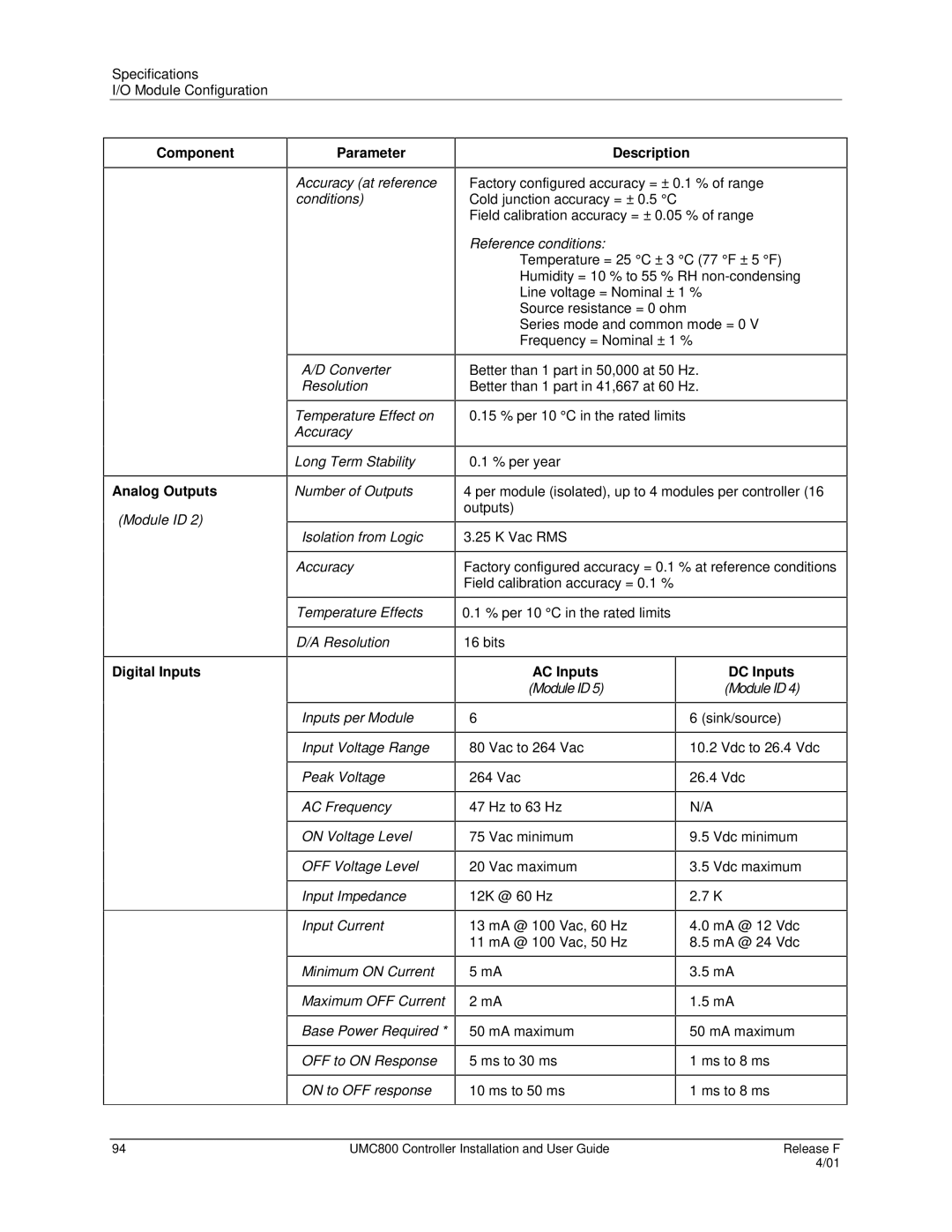
Component
Analog Outputs
(Module ID 2)
Parameter
Accuracy (at reference conditions)
A/D Converter
Resolution
Temperature Effect on Accuracy
Long Term Stability
Number of Outputs
Isolation from Logic
Accuracy
Temperature Effects
D/A Resolution
Description
Factory configured accuracy = ± 0.1 % of range Cold junction accuracy = ± 0.5 °C
Field calibration accuracy = ± 0.05 % of range
Reference conditions:
Temperature = 25 °C ± 3 °C (77 °F ± 5 °F) Humidity = 10 % to 55 % RH
Source resistance = 0 ohm
Series mode and common mode = 0 V Frequency = Nominal ± 1 %
Better than 1 part in 50,000 at 50 Hz.
Better than 1 part in 41,667 at 60 Hz.
0.15 % per 10 °C in the rated limits
0.1 % per year
4 per module (isolated), up to 4 modules per controller (16 outputs)
3.25 K Vac RMS
Factory configured accuracy = 0.1 % at reference conditions Field calibration accuracy = 0.1 %
0.1% per 10 °C in the rated limits
16 bits
Digital Inputs
Inputs per Module
Input Voltage Range
Peak Voltage
AC Frequency
ON Voltage Level
OFF Voltage Level
Input Impedance
Input Current
Minimum ON Current
Maximum OFF Current
Base Power Required *
OFF to ON Response
ON to OFF response
AC Inputs
(Module ID 5)
6
80 Vac to 264 Vac
264 Vac
47 Hz to 63 Hz
75 Vac minimum
20 Vac maximum
12K @ 60 Hz
13 mA @ 100 Vac, 60 Hz
11 mA @ 100 Vac, 50 Hz
5mA
2mA
50mA maximum
5ms to 30 ms
10ms to 50 ms
DC Inputs
(Module ID 4)
6 (sink/source)
10.2Vdc to 26.4 Vdc
26.4Vdc
N/A
9.5Vdc minimum
3.5Vdc maximum
2.7K
4.0mA @ 12 Vdc
8.5mA @ 24 Vdc
3.5mA
1.5mA
50 mA maximum
1 ms to 8 ms
1 ms to 8 ms
94 | UMC800 Controller Installation and User Guide | Release F |
|
| 4/01 |