Mounting and Wiring
Signal Wiring
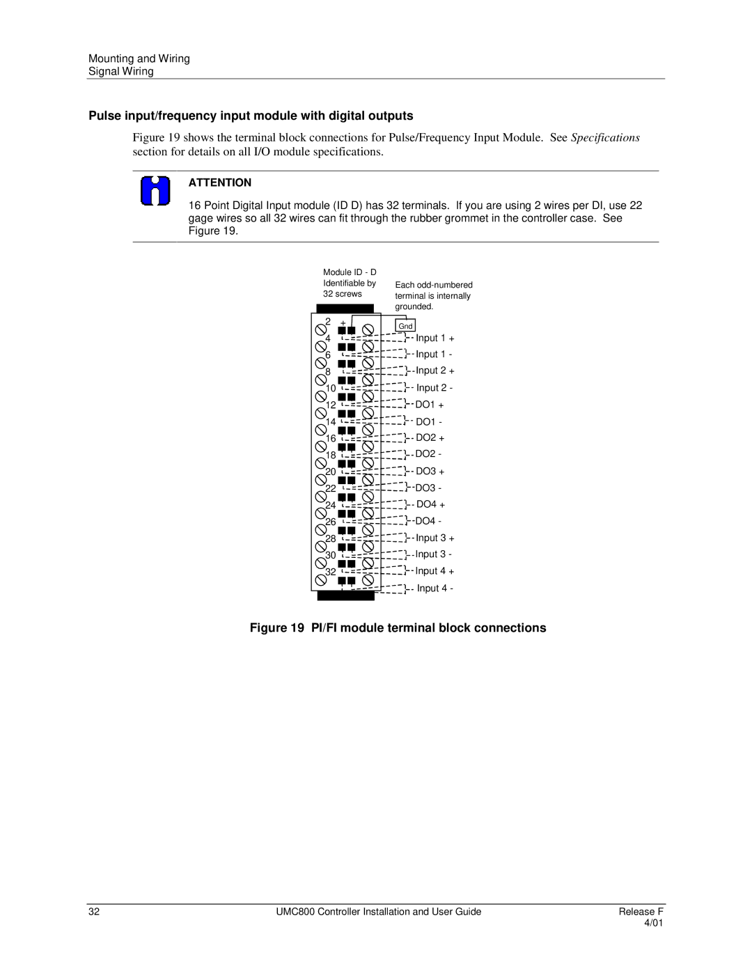
Pulse input/frequency input module with digital outputs
Figure 19 shows the terminal block connections for Pulse/Frequency Input Module. See Specifications section for details on all I/O module specifications.
ATTENTION
16 Point Digital Input module (ID D) has 32 terminals. If you are using 2 wires per DI, use 22 gage wires so all 32 wires can fit through the rubber grommet in the controller case. See Figure 19.
| Module ID - D |
| |
| Identifiable by | Each | |
| 32 screws | terminal is internally | |
|
|
| grounded. |
|
|
| |
2 | + | Gnd |
4 |
| Input 1 + |
6![]()
![]()
![]()
![]()
![]()
![]()
![]()
![]()
![]()
![]()
![]()
![]() Input 1 -
Input 1 -
8![]()
![]()
![]()
![]()
![]()
![]()
![]()
![]()
![]()
![]()
![]()
![]() Input 2 +
Input 2 +
10![]()
![]()
![]()
![]()
![]()
![]()
![]()
![]()
![]()
![]()
![]()
![]()
![]() Input 2 -
Input 2 -
12![]()
![]()
![]()
![]()
![]()
![]()
![]()
![]()
![]()
![]()
![]()
![]()
![]() DO1 +
DO1 +
14![]()
![]()
![]()
![]()
![]()
![]()
![]()
![]()
![]()
![]()
![]()
![]()
![]() DO1 -
DO1 -
16![]()
![]()
![]()
![]()
![]()
![]()
![]()
![]()
![]()
![]()
![]()
![]() DO2 +
DO2 +
18![]()
![]()
![]()
![]()
![]()
![]()
![]()
![]()
![]()
![]()
![]()
![]() DO2 -
DO2 -
20![]()
![]()
![]()
![]()
![]()
![]()
![]()
![]()
![]()
![]()
![]()
![]() DO3 +
DO3 +
22![]()
![]()
![]()
![]()
![]()
![]()
![]()
![]()
![]()
![]()
![]()
![]()
![]() DO3 -
DO3 -
24![]()
![]()
![]()
![]()
![]()
![]()
![]()
![]()
![]()
![]()
![]()
![]() DO4 +
DO4 +
26![]()
![]()
![]()
![]()
![]()
![]()
![]()
![]()
![]()
![]()
![]()
![]() DO4 -
DO4 -
28![]()
![]()
![]()
![]()
![]()
![]()
![]()
![]()
![]()
![]()
![]()
![]() Input 3 +
Input 3 +
30![]()
![]()
![]()
![]()
![]()
![]()
![]()
![]()
![]()
![]()
![]()
![]() Input 3 -
Input 3 -
32![]()
![]()
![]()
![]()
![]()
![]()
![]()
![]()
![]()
![]()
![]()
![]() Input 4 +
Input 4 +
Input 4 -
Figure 19 PI/FI module terminal block connections
32 | UMC800 Controller Installation and User Guide | Release F |
|
| 4/01 |