Specifications
I/O Module Configuration
Component
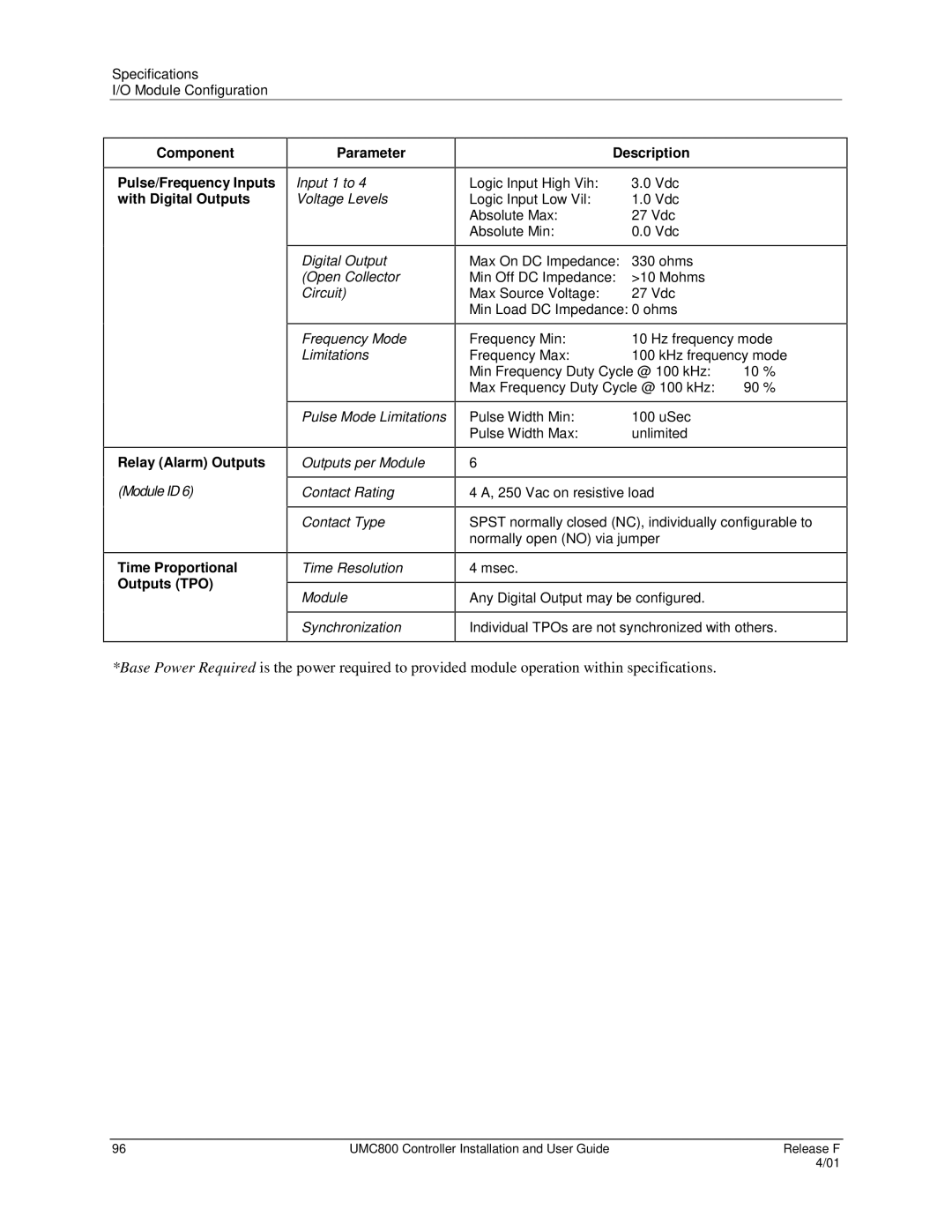
Pulse/Frequency Inputs with Digital Outputs
Parameter
Input 1 to 4 Voltage Levels
| Description |
|
|
Logic Input High Vih: | 3.0 Vdc |
Logic Input Low Vil: | 1.0 Vdc |
Absolute Max: | 27 Vdc |
Absolute Min: | 0.0 Vdc |
|
|
Digital Output
(Open Collector
Circuit)
Frequency Mode Limitations
Max On DC Impedance: 330 ohms
Min Off DC Impedance: >10 Mohms
Max Source Voltage: 27 Vdc
Min Load DC Impedance: 0 ohms
Frequency Min: | 10 Hz frequency mode | |
Frequency Max: | 100 kHz frequency mode | |
Min Frequency Duty Cycle @ 100 kHz: | 10 % | |
Max Frequency Duty Cycle @ 100 kHz: | 90 % | |
|
|
|
Relay (Alarm) Outputs
(Module ID 6)
Time Proportional Outputs (TPO)
Pulse Mode Limitations
Outputs per Module
Contact Rating
Contact Type
Time Resolution
Module
Synchronization
Pulse Width Min: | 100 uSec |
Pulse Width Max: | unlimited |
|
|
6 |
|
|
|
4 A, 250 Vac on resistive load
SPST normally closed (NC), individually configurable to normally open (NO) via jumper
4 msec.
Any Digital Output may be configured.
Individual TPOs are not synchronized with others.
*Base Power Required is the power required to provided module operation within specifications.
96 | UMC800 Controller Installation and User Guide | Release F |
|
| 4/01 |
