Operation Status Indicators
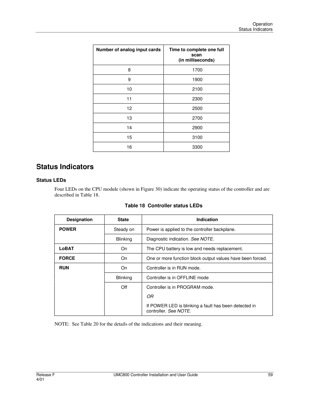
Number of analog input cards
8
9
10
11
12
13
14
15
16
Time to complete one full
scan
(in milliseconds)
1700
1900
2100
2300
2500
2700
2900
3100
3300
Status Indicators
Status LEDs
Four LEDs on the CPU module (shown in Figure 30) indicate the operating status of the controller and are described in Table 18.
Table 18 Controller status LEDs
Designation
POWER
LoBAT
FORCE
RUN
State
Steady on
Blinking
On
On
On
Blinking
Off
Indication
Power is applied to the controller backplane.
Diagnostic indication. See NOTE.
The CPU battery is low and needs replacement.
One or more function block output values have been forced.
Controller is in RUN mode.
Controller is in OFFLINE mode
Controller is in PROGRAM mode.
OR
If POWER LED is blinking a fault has been detected in controller. See NOTE.
NOTE: See Table 20 for the details of the indications and their meaning.
Release F | UMC800 Controller Installation and User Guide | 59 |
4/01 |
|
|
