Maintenance Replacement Procedures
Step
18
Action
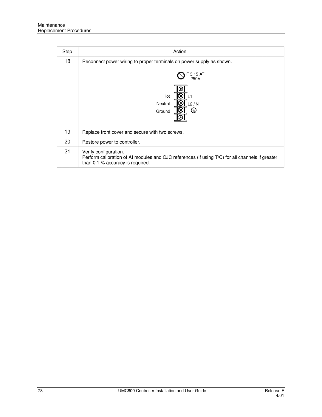
Reconnect power wiring to proper terminals on power supply as shown.
| F 3,15 AT |
| 250V |
Hot | L1 |
Neutral | L2 / N |
Ground |
|
19
20
21
Replace front cover and secure with two screws.
Restore power to controller.
Verify configuration.
Perform calibration of AI modules and CJC references (if using T/C) for all channels if greater than 0.1 % accuracy is required.
78 | UMC800 Controller Installation and User Guide | Release F |
|
| 4/01 |