Mounting and Wiring
Wiring Communication Links
COMM A and B connectors (optional)
The CPU module equipped with the optional communication board provides two additional RS 485 communications ports with Modbus RTU protocol support. COMM A port allows the UMC800 controller to network with up to 31 other slave UMC800 controllers and devices on a Modbus link. COMM B port allows the UMC800 controller to be a master to up to 16 slave UMC800 controllers and devices on a Modbus link.
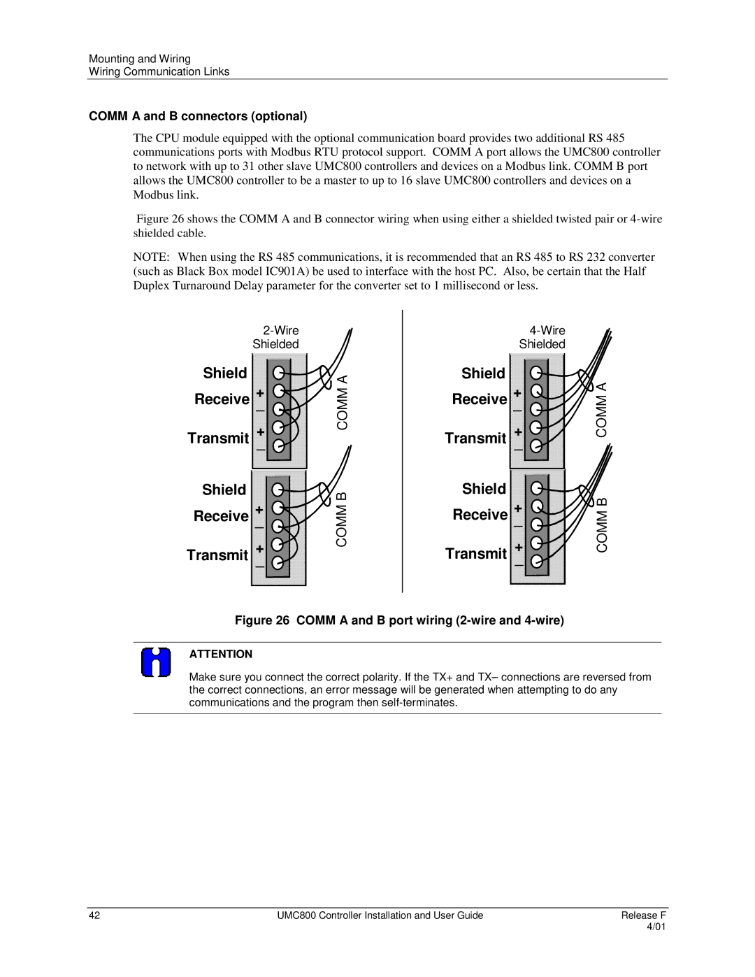
Figure 26 shows the COMM A and B connector wiring when using either a shielded twisted pair or 4-wire shielded cable.
NOTE: When using the RS 485 communications, it is recommended that an RS 485 to RS 232 converter (such as Black Box model IC901A) be used to interface with the host PC. Also, be certain that the Half Duplex Turnaround Delay parameter for the converter set to 1 millisecond or less.
Shield
+
Receive _
+
Transmit _
Shield
+
Receive _
+
Transmit _
COMM A
COMM B
Shield
+
Receive _
+
Transmit _
Shield
+
Receive _
+
Transmit _
COMM A
COMM B
Figure 26 COMM A and B port wiring (2-wire and 4-wire)
ATTENTION
Make sure you connect the correct polarity. If the TX+ and TX– connections are reversed from the correct connections, an error message will be generated when attempting to do any communications and the program then
42 | UMC800 Controller Installation and User Guide | Release F |
|
| 4/01 |