Maintenance
Replacement Procedures
Replacing I/O modules
If any I/O modules need to be replaced, follow the steps in the table below.
Step
1
2
3
Action
Remove power from controller.
Remove front cover by loosening the two screws at the top of the enclosure.
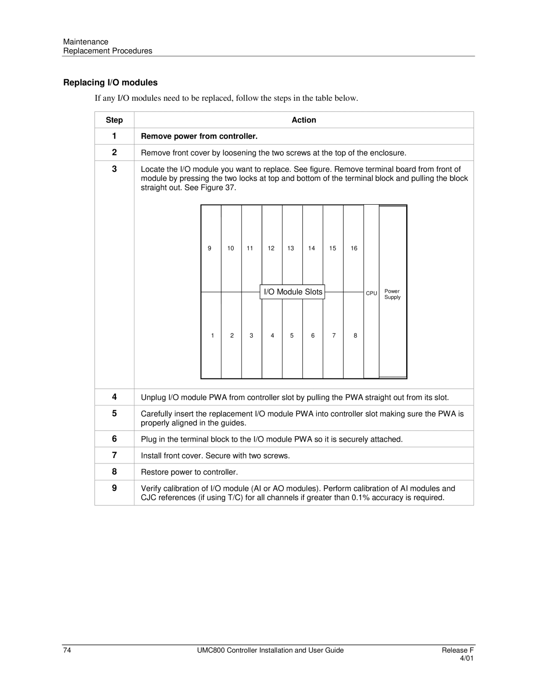
Locate the I/O module you want to replace. See figure. Remove terminal board from front of module by pressing the two locks at top and bottom of the terminal block and pulling the block straight out. See Figure 37.
9 10
11
12
13
14
15
16
I/O Module Slots
CPU Power Supply
1 2
3
4
5
6
7
8
4
5
6
7
8
9
Unplug I/O module PWA from controller slot by pulling the PWA straight out from its slot.
Carefully insert the replacement I/O module PWA into controller slot making sure the PWA is properly aligned in the guides.
Plug in the terminal block to the I/O module PWA so it is securely attached.
Install front cover. Secure with two screws.
Restore power to controller.
Verify calibration of I/O module (AI or AO modules). Perform calibration of AI modules and CJC references (if using T/C) for all channels if greater than 0.1% accuracy is required.
74 | UMC800 Controller Installation and User Guide | Release F |
|
| 4/01 |