Mounting and Wiring Signal Wiring
| Module B |
| |
| Identifiable by | Each | |
| 32 screws | terminal is internally | |
|
|
| grounded. |
|
|
| |
2 + | Gnd |
4![]()
![]()
![]()
![]()
![]()
![]()
![]()
![]() DI 16
DI 16
6![]()
![]()
![]()
![]()
![]()
![]()
![]()
![]()
![]() DI 15
DI 15
8![]()
![]()
![]()
![]()
![]()
![]()
![]()
![]()
![]()
![]() DI 14
DI 14
10![]()
![]()
![]()
![]()
![]()
![]()
![]()
![]()
![]() DI 13
DI 13
12![]()
![]()
![]()
![]()
![]()
![]()
![]()
![]()
![]()
![]() DI 12
DI 12
14![]()
![]()
![]()
![]()
![]()
![]()
![]()
![]()
![]()
![]() DI 11
DI 11
16![]()
![]()
![]()
![]()
![]()
![]()
![]()
![]()
![]() DI 10
DI 10
18![]()
![]()
![]()
![]()
![]()
![]()
![]()
![]()
![]() DI 9
DI 9
20![]()
![]()
![]()
![]()
![]()
![]()
![]()
![]()
![]() DI 8
DI 8
22![]()
![]()
![]()
![]()
![]()
![]()
![]()
![]()
![]()
![]() DI 7
DI 7
24![]()
![]()
![]()
![]()
![]()
![]()
![]()
![]()
![]()
![]() DI 6
DI 6
26![]()
![]()
![]()
![]()
![]()
![]()
![]()
![]()
![]()
![]() DI 5
DI 5
28![]()
![]()
![]()
![]()
![]()
![]()
![]()
![]()
![]()
![]() DI 4
DI 4
30![]()
![]()
![]()
![]()
![]()
![]()
![]()
![]()
![]()
![]() DI 3
DI 3
32![]()
![]()
![]()
![]()
![]()
![]()
![]()
![]()
![]()
![]() DI 2
DI 2
![]()
![]()
![]()
![]()
![]() DI 1
DI 1
Module ID B (16 DI)
Logic Input (Contact Closure)
For 2 wires per DI, must use
R
Logic
Field Wiring
Gnd
+ VCC
Dry SW
Module ID B (16 DI)
Logic Input (Contact Closure)
For 1 common wire for all DIs, use
Field Wiring
R
Dry SW |
|
|
|
|
| Logic | |
|
|
|
|
|
|
|
|
Gnd
+ VCC
•One wire per DI. Each wire goes to Marshalling field connector (user provided).
•One common wire from Marshalling field
connector to any ground connector on the 16 pt. DI terminal.
Marshalling field connector
Module ID | 12 | DI 6 |
#3, 4, or 5 | 11 | |
|
| |
| 10 |
|
|
| DI 5 |
| 9 |
|
| 8 | DI 4 |
| 7 | |
|
| |
| 6 | DI 3 |
| 5 | |
|
| |
| 4 |
|
|
| DI 2 |
| 3 |
|
| 2 | DI 1 |
| 1 | |
|
|
Module ID #3
Logic Input (Contact Closure)
Field Wiring
R
Gnd
+ VCC
Module ID #4
DC Input (24 Vdc)
Field Wiring | + VCC |
| + |
+ | R |
| |
24V |
|
- | - |
|
Module ID #5
AC Input (120/240 Vdc)
Field Wiring | + VCC |
|
Dry SW
R
L1
L2 ![]()
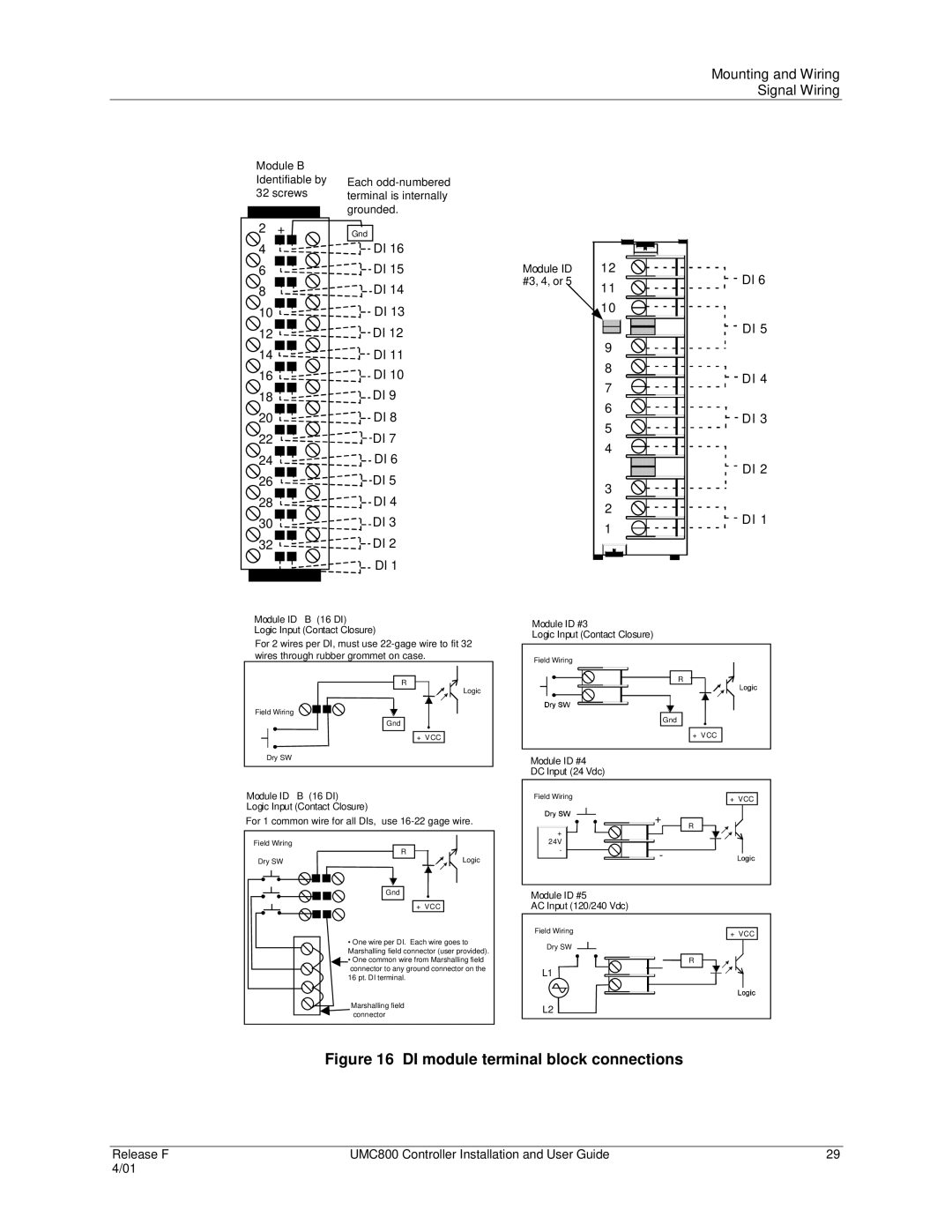
Figure 16 DI module terminal block connections
Release F | UMC800 Controller Installation and User Guide | 29 |
4/01 |
|
|
