Equipment Identification
Controller Components
Equipment Identification
Controller Components
Enclosure
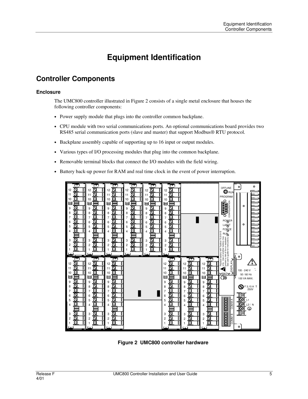
The UMC800 controller illustrated in Figure 2 consists of a single metal enclosure that houses the following controller components:
•Power supply module that plugs into the controller common backplane.
•CPU module with two serial communications ports. An optional communications board provides two RS485 serial communication ports (slave and master) that support Modbus® RTU protocol.
•Backplane assembly capable of supporting up to 16 input or output modules.
•Various types of I/O processing modules that plug into the common backplane.
•Removable terminal blocks that connect the I/O modules with the field wiring.
•Battery
12
11
10
9
8
7
6
5
4
3
2
1
12
11
10
9
8
7
6
5
4
3
2
1
12
11
10
9
8
7
6
5
4
3
2
1
12
11
10
9
8
7
6
5
4
3
2
1
12
11
10
9
8
7
6
5
4
3
2
1
12
11
10
9
8
7
6
5
4
3
2
1
OFFLINE ![]() RUN
RUN
PROGRAM ![]() CONFIGURATION POWER
CONFIGURATION POWER
LoBAT
FORCE
TL5101/S RUN Tadiran may explosion. instructions. with batteryanother orfire for battery of guide ofUse riska user’s
12
11
10
9
12
11
10
9
12
11
10
9
12
11
10
9
12
11
10
9
12
11
10
9
Replace only. present See DISPLAY
![]() BAT
BAT![]()
![]()
_
100 - 240 V ~
50 / 60 Hz
100 VA MAX.
8
7
6
5
4
3
2
1
8
7
6
5
4
3
2
1
8
7
6
5
4
3
2
1
8
7
6
5
4
3
2
1
8
7
6
5
4
3
2
1
8
7
6
5
4
3
2
1
![]()
![]() F 3,15 A T
F 3,15 A T ![]()
![]() 250V
250V
A | L1 | |
M | ||
| ||
COM | L2 / N | |
| ||
COMM B |
|
Figure 2 UMC800 controller hardware
Release F | UMC800 Controller Installation and User Guide | 5 |
4/01 |
|
|
