Maintenance
Replacement Procedures
Replacing the power supply module
Step
1
2
3
4
5
6
7
8
9
Action
Remove power from controller.
Disconnect power wiring from power supply terminals.
Remove front cover by loosening the two screws at the top of the enclosure.
Remove five screws on the front of power supply securing the CPU module and power supply.
Unplug CPU module from controller slot by pulling it straight out from its slot.
Unplug power supply module from controller by pulling it straight out from its slot.
Plug in the replacement power supply into the enclosure slot and carefully insert CPU module into its slot.
Secure power supply and CPU with five screws.
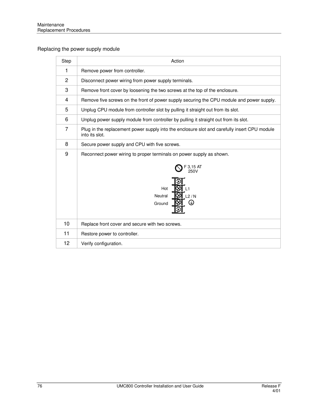
Reconnect power wiring to proper terminals on power supply as shown.
| F 3,15 AT |
| 250V |
Hot | L1 |
Neutral | L2 / N |
Ground |
|
10
11
12
Replace front cover and secure with two screws.
Restore power to controller.
Verify configuration.
76 | UMC800 Controller Installation and User Guide | Release F |
|
| 4/01 |