Diagnostics and Troubleshooting
Fault Detection and Troubleclearing
Fault Detection and Troubleclearing
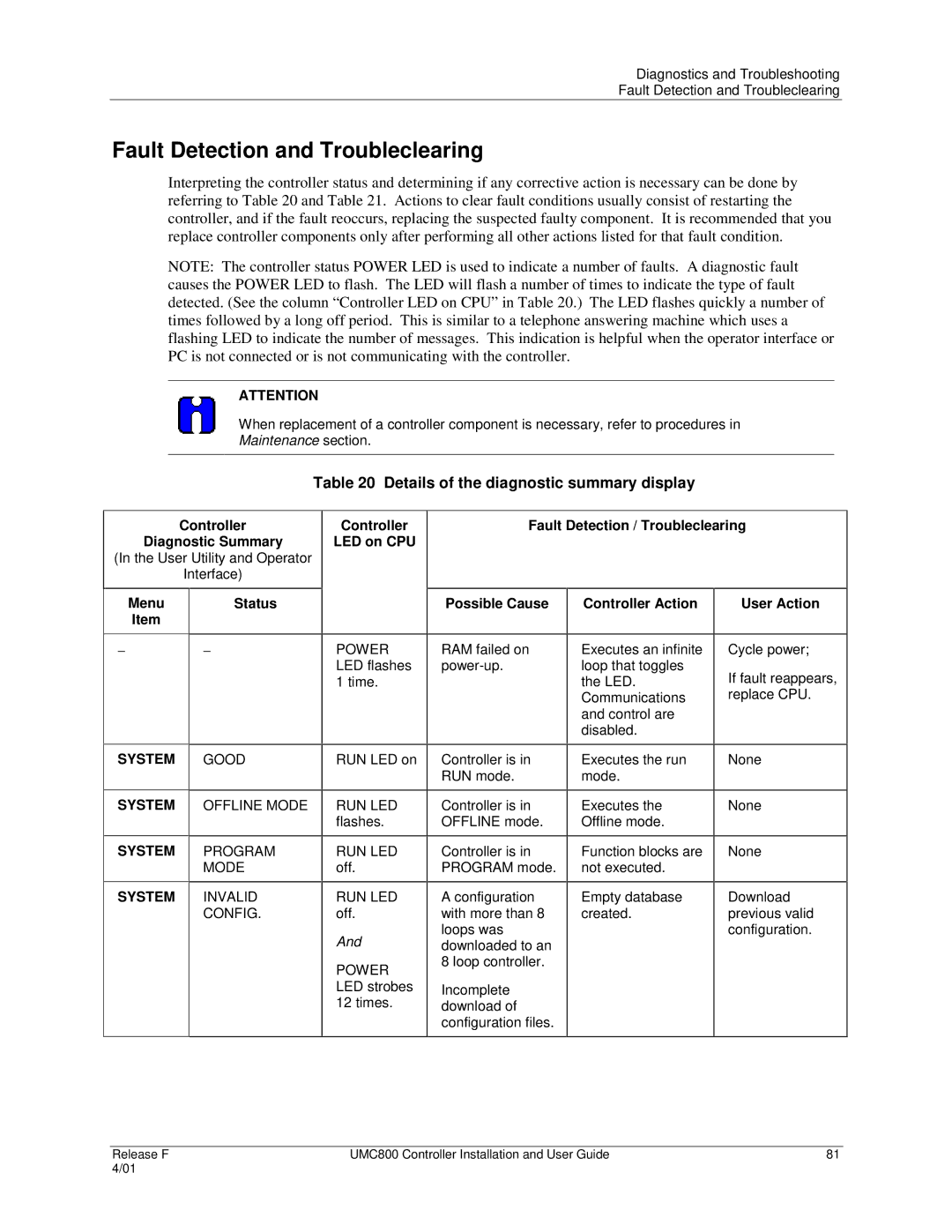
Interpreting the controller status and determining if any corrective action is necessary can be done by referring to Table 20 and Table 21. Actions to clear fault conditions usually consist of restarting the controller, and if the fault reoccurs, replacing the suspected faulty component. It is recommended that you replace controller components only after performing all other actions listed for that fault condition.
NOTE: The controller status POWER LED is used to indicate a number of faults. A diagnostic fault causes the POWER LED to flash. The LED will flash a number of times to indicate the type of fault detected. (See the column “Controller LED on CPU” in Table 20.) The LED flashes quickly a number of times followed by a long off period. This is similar to a telephone answering machine which uses a flashing LED to indicate the number of messages. This indication is helpful when the operator interface or PC is not connected or is not communicating with the controller.
ATTENTION
When replacement of a controller component is necessary, refer to procedures in
Maintenance section.
Table 20 Details of the diagnostic summary display
Controller
Diagnostic Summary
(In the User Utility and Operator
Interface)
Controller
LED on CPU
Fault Detection / Troubleclearing
Menu | Status |
Item |
|
|
|
− | − |
|
|
SYSTEM | GOOD |
|
|
SYSTEM | OFFLINE MODE |
|
|
SYSTEM | PROGRAM |
| MODE |
|
|
SYSTEM | INVALID |
| CONFIG. |
|
|
POWER LED flashes 1 time.
RUN LED on
RUN LED flashes.
RUN LED off.
RUN LED off.
And
POWER LED strobes 12 times.
Possible Cause
RAM failed on
Controller is in RUN mode.
Controller is in OFFLINE mode.
Controller is in PROGRAM mode.
Aconfiguration with more than 8 loops was downloaded to an 8 loop controller.
Incomplete download of configuration files.
Controller Action
Executes an infinite loop that toggles the LED. Communications and control are disabled.
Executes the run mode.
Executes the
Offline mode.
Function blocks are not executed.
Empty database created.
User Action
Cycle power;
If fault reappears, replace CPU.
None
None
None
Download previous valid configuration.
Release F | UMC800 Controller Installation and User Guide | 81 |
4/01 |
|
|
