Maintenance
Replacement Procedures
Replacing the backplane
Step
1
2
3
4
5
6
7
Action
Remove power from controller.
Disconnect power wiring from power supply terminals.
Remove front cover by loosening the two screws at the top of the enclosure.
Remove five screws on the front of power supply securing the CPU module and power supply.
Unplug CPU module from controller slot by pulling it straight out from its slot.
Unplug power supply module from enclosure by pulling it straight out from its slot.
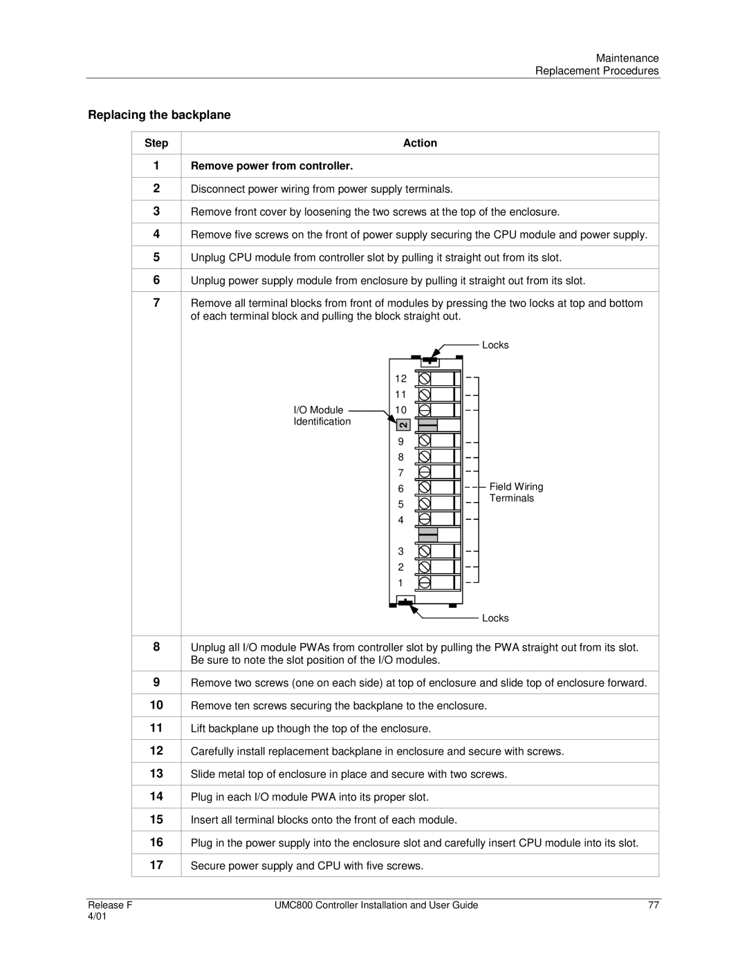
Remove all terminal blocks from front of modules by pressing the two locks at top and bottom of each terminal block and pulling the block straight out.
Locks
|
| 12 | |
|
| 11 | |
I/O Module |
| 10 | |
| |||
Identification |
| ||
| 2 | ||
9 |
|
8 |
|
7 |
|
6 | Field Wiring |
5 | Terminals |
| |
4 |
|
3 |
|
2 |
|
1 |
|
Locks
8
9
10
11
12
13
14
15
16
17
Unplug all I/O module PWAs from controller slot by pulling the PWA straight out from its slot. Be sure to note the slot position of the I/O modules.
Remove two screws (one on each side) at top of enclosure and slide top of enclosure forward.
Remove ten screws securing the backplane to the enclosure.
Lift backplane up though the top of the enclosure.
Carefully install replacement backplane in enclosure and secure with screws.
Slide metal top of enclosure in place and secure with two screws.
Plug in each I/O module PWA into its proper slot.
Insert all terminal blocks onto the front of each module.
Plug in the power supply into the enclosure slot and carefully insert CPU module into its slot.
Secure power supply and CPU with five screws.
Release F | UMC800 Controller Installation and User Guide | 77 |
4/01 |
|
|