Mounting and Wiring
Wiring Communication Links
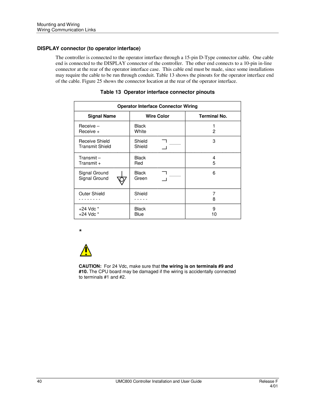
DISPLAY connector (to operator interface)
The controller is connected to the operator interface through a
Table 13 Operator interface connector pinouts
| Operator Interface Connector Wiring |
|
Signal Name | Wire Color | Terminal No. |
Receive –
Receive +
Receive Shield Transmit Shield
Transmit –
Transmit +
Signal Ground Signal Ground
Outer Shield
- - - - - - - -
+24 Vdc *
+24 Vdc *
Black White
Shield Shield
Black Red
Black Green
Shield
- - - - -
Black Blue
1
2
3
4
5
6
7
8
9
10
*
CAUTION: For 24 Vdc, make sure that the wiring is on terminals #9 and #10. The CPU board may be damaged if the wiring is accidentally connected to terminals #1 and #2.
40 | UMC800 Controller Installation and User Guide | Release F |
|
| 4/01 |