Mounting and Wiring
Plug-in Module Locations
Common backplane
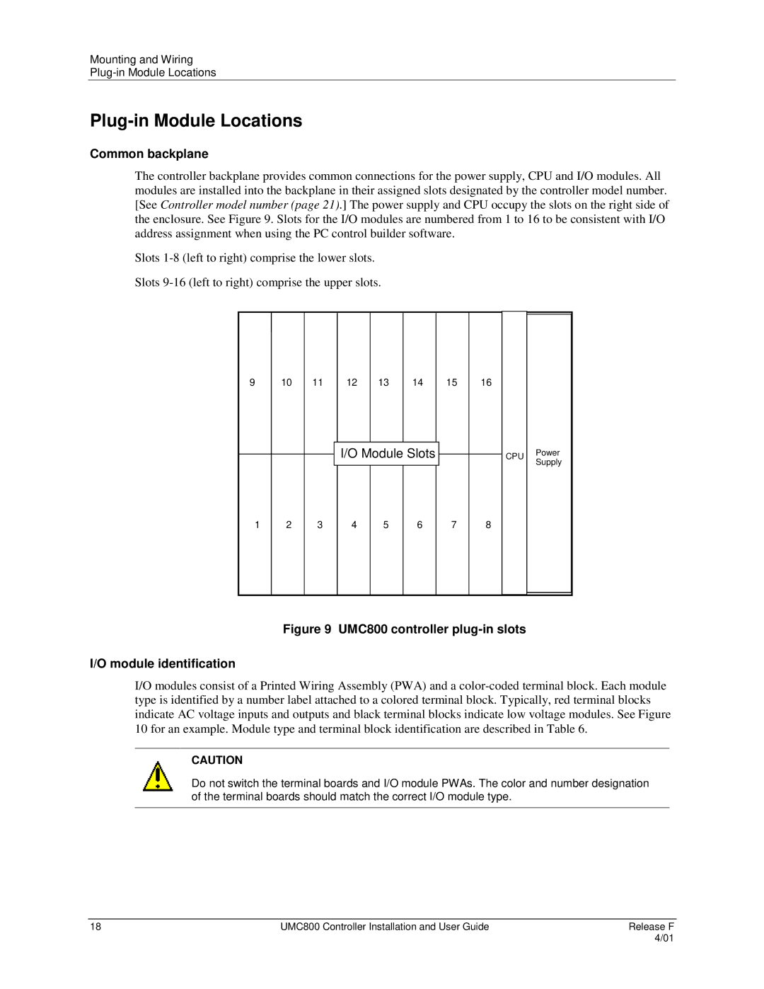
The controller backplane provides common connections for the power supply, CPU and I/O modules. All modules are installed into the backplane in their assigned slots designated by the controller model number. [See Controller model number (page 21).] The power supply and CPU occupy the slots on the right side of the enclosure. See Figure 9. Slots for the I/O modules are numbered from 1 to 16 to be consistent with I/O address assignment when using the PC control builder software.
Slots
Slots
9 10
11
12
13
14
15
16
I/O Module Slots
CPU Power Supply
1 2
3
4
5
6
7
8
Figure 9 UMC800 controller plug-in slots
I/O module identification
I/O modules consist of a Printed Wiring Assembly (PWA) and a
CAUTION
Do not switch the terminal boards and I/O module PWAs. The color and number designation of the terminal boards should match the correct I/O module type.
18 | UMC800 Controller Installation and User Guide | Release F |
|
| 4/01 |
