Diagnostics and Troubleshooting Fault Detection and Troubleclearing
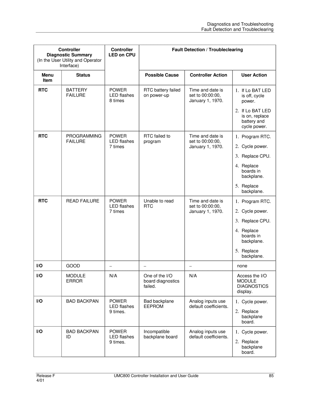
Controller
Diagnostic Summary
(In the User Utility and Operator
Interface)
Menu | Status |
Item |
|
|
|
Controller | Fault Detection / Troubleclearing | ||
LED on CPU |
|
|
|
|
|
|
|
| Possible Cause | Controller Action | User Action |
|
|
|
|
RTC | BATTERY |
| FAILURE |
|
|
RTC | PROGRAMMING |
| FAILURE |
|
|
RTC | READ FAILURE |
|
|
I/O | GOOD |
|
|
I/O | MODULE |
| ERROR |
|
|
I/O | BAD BACKPAN |
|
|
I/O | BAD BACKPAN |
| ID |
|
|
POWER LED flashes 8 times
POWER LED flashes 7 times
POWER LED flashes 7 times
−
N/A
POWER LED flashes 9 times.
POWER LED flashes 9 times.
RTC battery failed on
RTC failed to program
Unable to read
RTC
−
One of the I/O board diagnostics failed.
Bad backplane
EEPROM
Incompatible backplane board
Time and date is set to 00:00:00, January 1, 1970.
Time and date is set to 00:00:00, January 1, 1970.
Time and date is set to 00:00:00, January 1, 1970.
−
N/A
Analog inputs use default coefficients.
Analog inputs use default coefficients.
1.If Lo BAT LED is off, cycle power.
2.If Lo BAT LED is on, replace battery and cycle power.
1.Program RTC.
2.Cycle power.
3.Replace CPU.
4.Replace boards in backplane.
5.Replace backplane.
1.Program RTC.
2.Cycle power.
3.Replace CPU.
4.Replace boards in backplane.
5.Replace backplane.
none
Access the I/O
MODULE DIAGNOSTICS display.
1.Cycle power.
2.Replace backplane board.
1.Cycle power.
2.Replace backplane board.
Release F | UMC800 Controller Installation and User Guide | 85 |
4/01 |
|
|