Maintenance Replacement Procedures
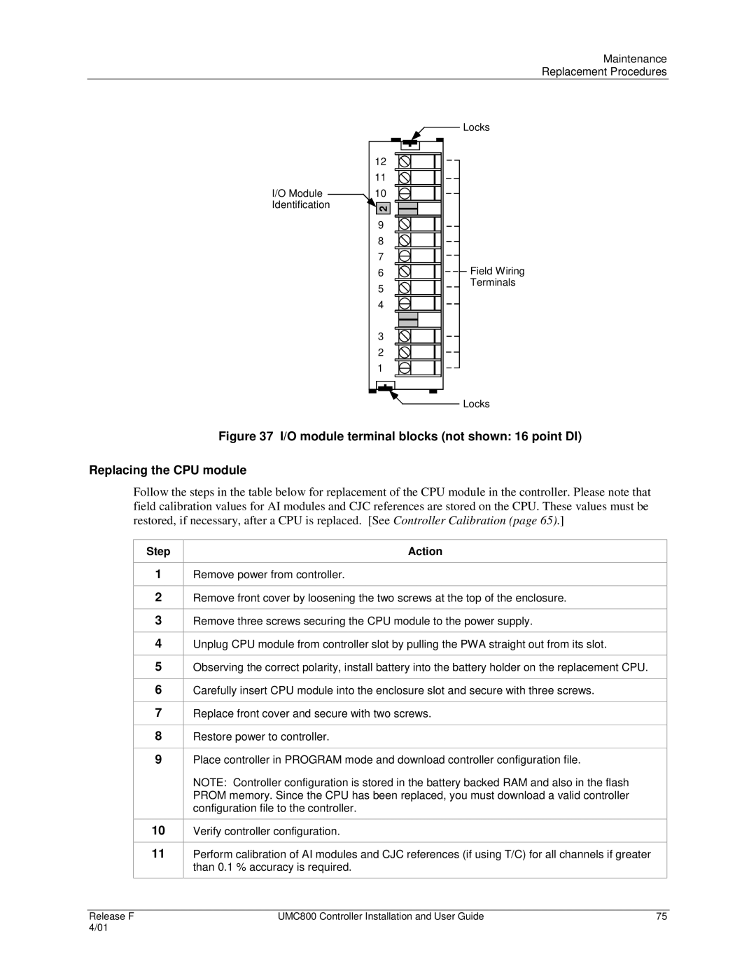
I/O Module Identification
Locks
12
11
![]() 10
10
2 |
|
9 |
|
8 |
|
7 |
|
6 | Field Wiring |
5 | Terminals |
| |
4 |
|
3 |
|
2 |
|
1 |
|
| Locks |
Figure 37 I/O module terminal blocks (not shown: 16 point DI)
Replacing the CPU module
Follow the steps in the table below for replacement of the CPU module in the controller. Please note that field calibration values for AI modules and CJC references are stored on the CPU. These values must be restored, if necessary, after a CPU is replaced. [See Controller Calibration (page 65).]
Step
1
2
3
4
5
6
7
8
9
10
11
Action
Remove power from controller.
Remove front cover by loosening the two screws at the top of the enclosure.
Remove three screws securing the CPU module to the power supply.
Unplug CPU module from controller slot by pulling the PWA straight out from its slot.
Observing the correct polarity, install battery into the battery holder on the replacement CPU.
Carefully insert CPU module into the enclosure slot and secure with three screws.
Replace front cover and secure with two screws.
Restore power to controller.
Place controller in PROGRAM mode and download controller configuration file.
NOTE: Controller configuration is stored in the battery backed RAM and also in the flash PROM memory. Since the CPU has been replaced, you must download a valid controller configuration file to the controller.
Verify controller configuration.
Perform calibration of AI modules and CJC references (if using T/C) for all channels if greater than 0.1 % accuracy is required.
Release F | UMC800 Controller Installation and User Guide | 75 |
4/01 |
|
|
