Mounting and Wiring
Wiring Communication Links
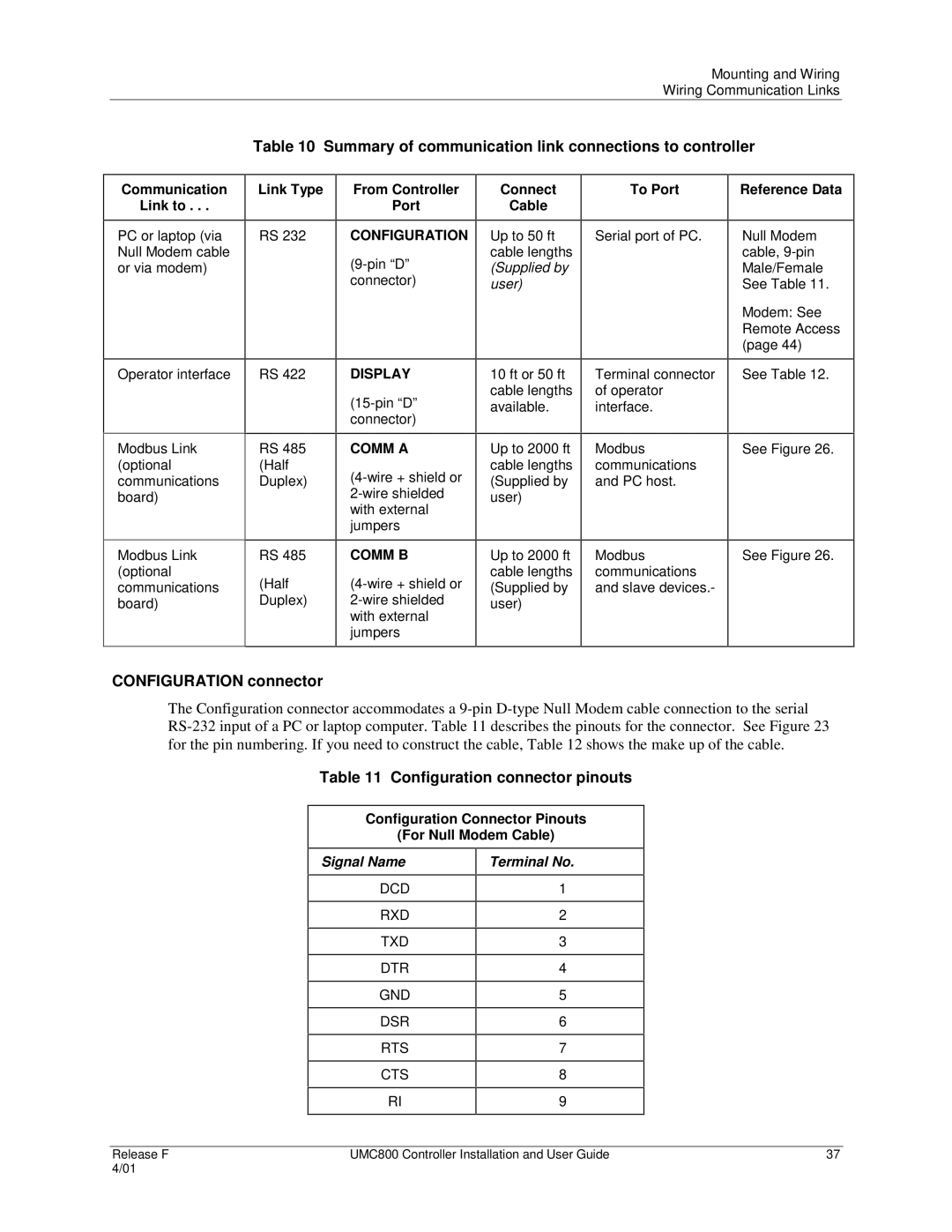
Table 10 Summary of communication link connections to controller
Communication
Link to . . .
PC or laptop (via Null Modem cable or via modem)
Operator interface
Modbus Link (optional communications board)
Modbus Link (optional communications board)
Link Type
RS 232
RS 422
RS 485 (Half Duplex)
RS 485
(Half
Duplex)
From Controller
Port
CONFIGURATION
DISPLAY
COMM A
COMM B
Connect | To Port |
Cable |
|
|
|
Up to 50 ft | Serial port of PC. |
cable lengths |
|
(Supplied by |
|
user) |
|
|
|
10 ft or 50 ft | Terminal connector |
cable lengths | of operator |
available. | interface. |
|
|
Up to 2000 ft | Modbus |
cable lengths | communications |
(Supplied by | and PC host. |
user) |
|
|
|
Up to 2000 ft | Modbus |
cable lengths | communications |
(Supplied by | and slave devices.- |
user) |
|
|
|
Reference Data
Null Modem cable,
Modem: See Remote Access (page 44)
See Table 12.
See Figure 26.
See Figure 26.
CONFIGURATION connector
The Configuration connector accommodates a
Table 11 Configuration connector pinouts
Configuration Connector Pinouts
(For Null Modem Cable)
Signal Name
DCD
RXD
TXD
DTR
GND
DSR
RTS
CTS
RI
Terminal No.
1
2
3
4
5
6
7
8
9
Release F | UMC800 Controller Installation and User Guide | 37 |
4/01 |
|
|