Equipment Identification

Control Builder

Control Builder

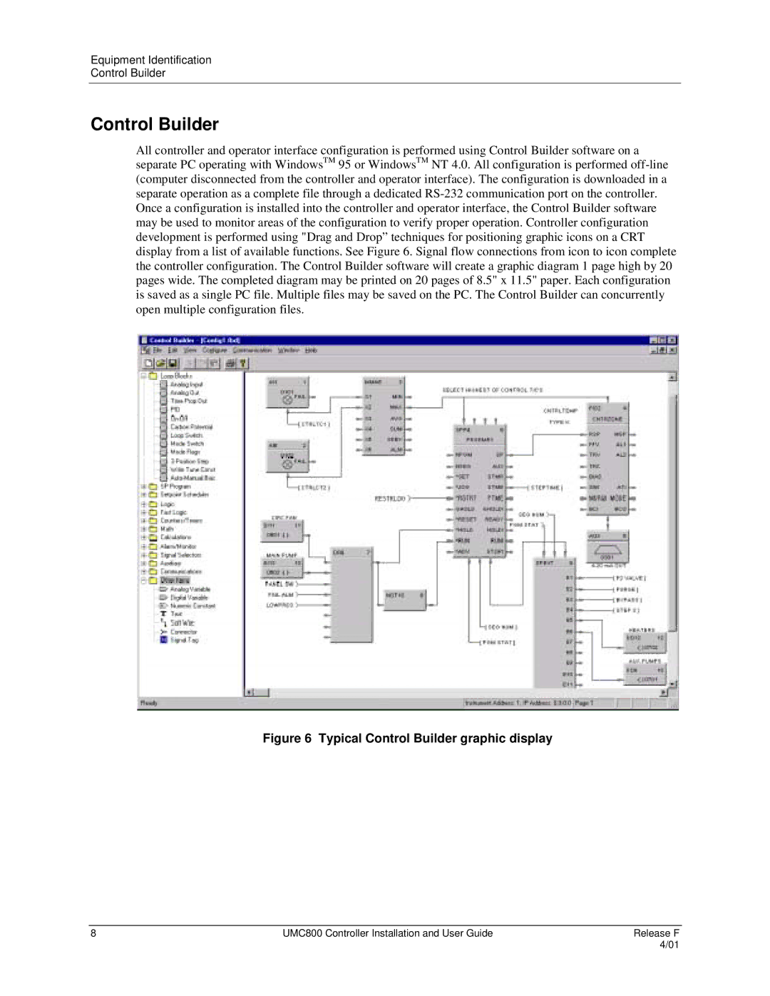
All controller and operator interface configuration is performed using Control Builder software on a separate PC operating with WindowsTM 95 or WindowsTM NT 4.0. All configuration is performed off-line (computer disconnected from the controller and operator interface). The configuration is downloaded in a separate operation as a complete file through a dedicated RS-232 communication port on the controller. Once a configuration is installed into the controller and operator interface, the Control Builder software may be used to monitor areas of the configuration to verify proper operation. Controller configuration development is performed using "Drag and Drop” techniques for positioning graphic icons on a CRT display from a list of available functions. See Figure 6. Signal flow connections from icon to icon complete the controller configuration. The Control Builder software will create a graphic diagram 1 page high by 20 pages wide. The completed diagram may be printed on 20 pages of 8.5" x 11.5" paper. Each configuration is saved as a single PC file. Multiple files may be saved on the PC. The Control Builder can concurrently open multiple configuration files.

Figure 6 Typical Control Builder graphic display

8

UMC800 Controller Installation and User Guide

Release F


4/01

Page 16
Image 16
Honeywell UMC800 manual Typical Control Builder graphic display