Operation Status Indicators
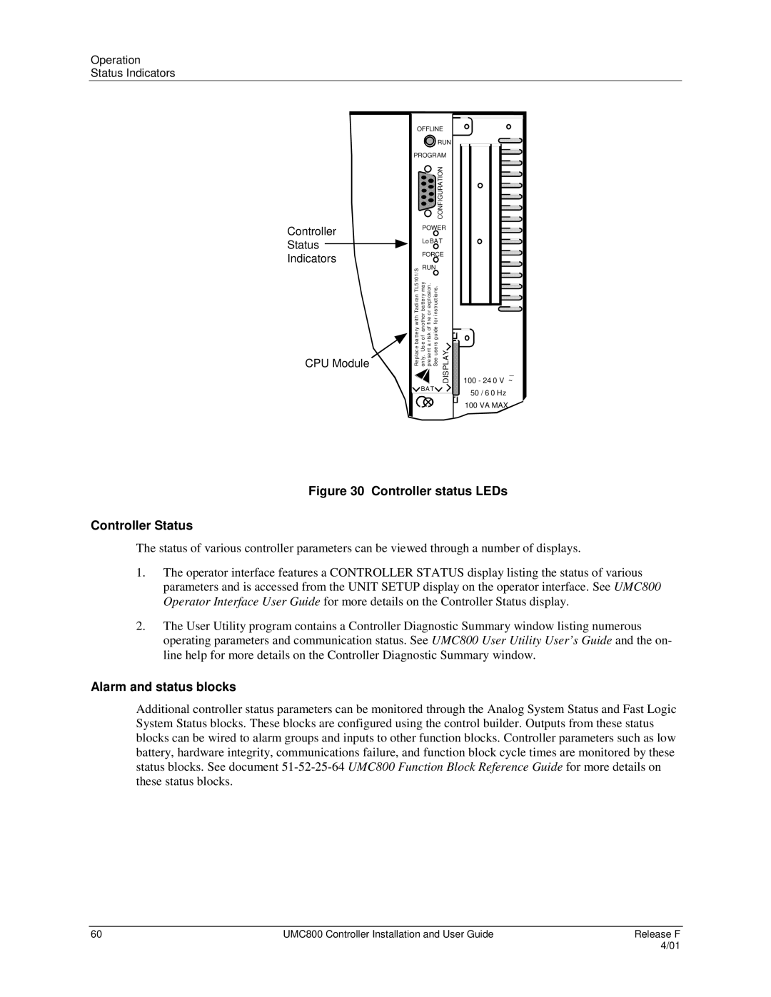
Controller
Status
Indicators
CPU Module
OFFLINE
![]() RUN PROGRAM
RUN PROGRAM
|
|
| CONFIGURATION |
|
| POWER | |||
| Lo BA T |
| ||
| FORCE | |||
with Tadi ran TL5101/S | RUN |
| ||
other ba tte ry ma y | fire or expl osion . | for instruct io ns. |
| |
Repl ac e ba ttery | on ly. Us e of an | pre se nt a r is k of | See use rs guide | DISPLAY |
![]() BA T
BA T![]()
_
100 - 24 0 V ~
50 / 6 0 Hz
100 VA MAX.
Figure 30 Controller status LEDs
Controller Status
The status of various controller parameters can be viewed through a number of displays.
1.The operator interface features a CONTROLLER STATUS display listing the status of various parameters and is accessed from the UNIT SETUP display on the operator interface. See UMC800 Operator Interface User Guide for more details on the Controller Status display.
2.The User Utility program contains a Controller Diagnostic Summary window listing numerous operating parameters and communication status. See UMC800 User Utility User’s Guide and the on- line help for more details on the Controller Diagnostic Summary window.
Alarm and status blocks
Additional controller status parameters can be monitored through the Analog System Status and Fast Logic System Status blocks. These blocks are configured using the control builder. Outputs from these status blocks can be wired to alarm groups and inputs to other function blocks. Controller parameters such as low battery, hardware integrity, communications failure, and function block cycle times are monitored by these status blocks. See document
60 | UMC800 Controller Installation and User Guide | Release F |
|
| 4/01 |