HP
Telnet options. Refer to the TCP/IP Connection Settings section in chapter 2 for details.
For a modem connection, select Modem, specify the communications port in the Connect To box, then click Configure to display configuration options. Refer to the Modem Connection Settings section in chapter 2 for details.
For a serial connection, select Serial, specify the communications port in the Connect To box, then click Configure for additional serial options. Refer to the Serial Connection Settings section in chapter 2 for details.
6.When you have specified the required settings in the New Connection dialog box, click the Connect button to make the connection.
Note: You can save these settings as a connection template using the Save Session As dialog box. Refer to the Setup Menus chapter for details.
Display Configuration
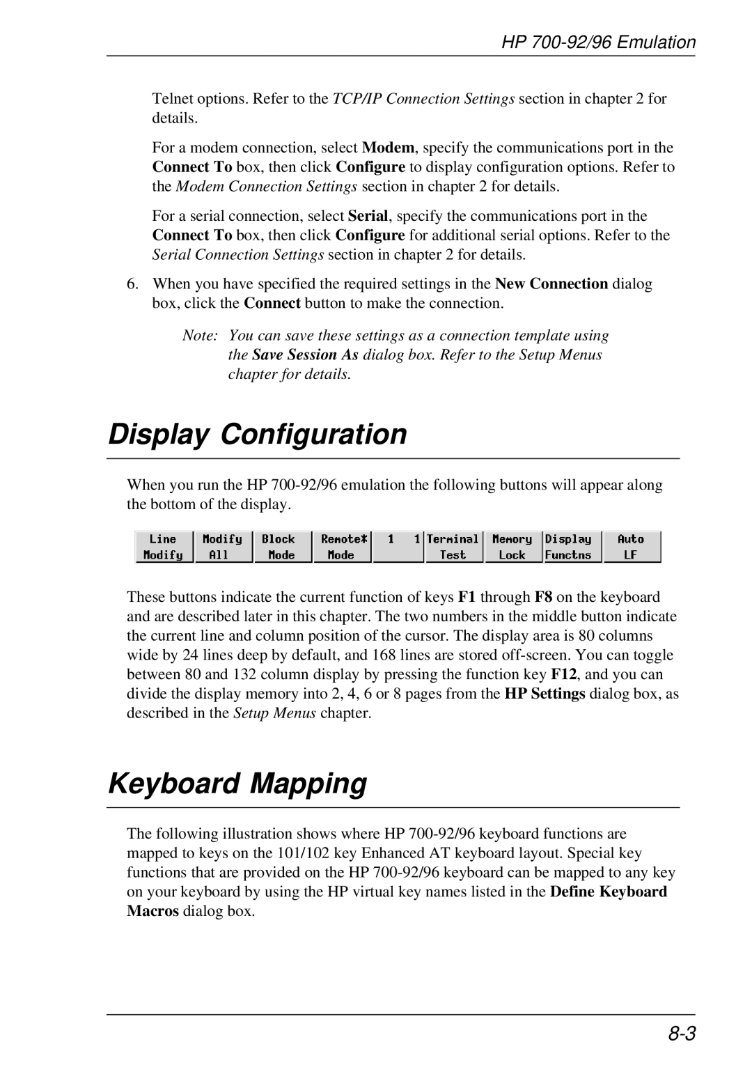
When you run the HP
These buttons indicate the current function of keys F1 through F8 on the keyboard and are described later in this chapter. The two numbers in the middle button indicate the current line and column position of the cursor. The display area is 80 columns wide by 24 lines deep by default, and 168 lines are stored
Keyboard Mapping
The following illustration shows where HP