Operation |
|
|
|
| |
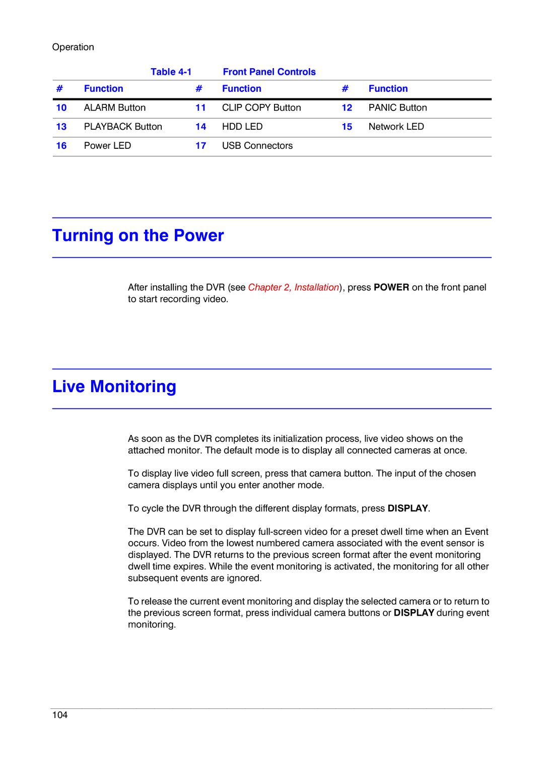
| Table |
| Front Panel Controls |
|
|
|
|
|
|
|
|
# | Function | # | Function | # | Function |
|
|
|
|
|
|
10 | ALARM Button | 11 | CLIP COPY Button | 12 | PANIC Button |
|
|
|
|
|
|
13 | PLAYBACK Button | 14 | HDD LED | 15 | Network LED |
|
|
|
|
|
|
16 | Power LED | 17 | USB Connectors |
|
|
|
|
|
|
|
|
Turning on the Power
After installing the DVR (see Chapter 2, Installation), press POWER on the front panel to start recording video.
Live Monitoring
As soon as the DVR completes its initialization process, live video shows on the attached monitor. The default mode is to display all connected cameras at once.
To display live video full screen, press that camera button. The input of the chosen camera displays until you enter another mode.
To cycle the DVR through the different display formats, press DISPLAY.
The DVR can be set to display
To release the current event monitoring and display the selected camera or to return to the previous screen format, press individual camera buttons or DISPLAY during event monitoring.
104