Installation
Table | Rear Panel Connections |
|
| |
# | Connection | # | Connection | |
|
|
|
| |
1 | Video input | 6 | Network/Ethernet port | |
|
|
|
| |
2 | Looping connectors | 7 | RS485 port for remote devices | |
|
|
|
| |
3 | Audio input x2; audio output x1 | 8 | Alarm inputs | |
|
|
|
| |
4 | Video main: BNC or VGA; | 9 | Alarm outputs | |
|
|
|
| |
|
|
|
| |
5 | Serial | 10 | Power cord connector | |
|
|
|
|
|
Your DVR can be used with either NTSC or PAL equipment.
Note You cannot mix NTSC and PAL equipment. For example, you cannot use a PAL camera and an NTSC monitor.
Connecting the Video Source
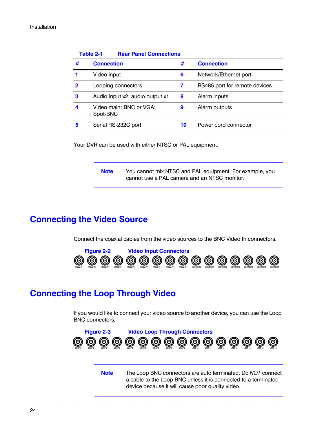
Connect the coaxial cables from the video sources to the BNC Video In connectors.
Figure 2-2 Video Input Connectors
Connecting the Loop Through Video
If you would like to connect your video source to another device, you can use the Loop BNC connectors.
Figure 2-3 Video Loop Through Connectors
Note The Loop BNC connectors are auto terminated. Do NOT connect a cable to the Loop BNC unless it is connected to a terminated device because it will cause poor quality video.
24
