Intel Storage System
User Guide
Disclaimers
Intel Server Boards and Server Chassis Safety Information
Safety Information
Intel Storage System SSR212PP User Guide
Contents
Installing PowerPath on the Server
Preparing Virtual Disks to Receive Data
Viii
List of Figures
Intel Storage System SSR212PP User Guide
List of Tables
Xii
Preface
About this Manual
Additional Information and Software
Xiv
Planning Your Fibre Channel Storage System Configuration
Topics in this procedure include
Provide a username and password for your storage system
Storage System Management Ports
Definitions
Customer-Installable Switch 1 Information
Fibre Channel Switch Information
Sample Switch Information Worksheet
Switch-to-Server-HBA Connections
SP-to-Switch Connections
Disk Information
Storage System Disk Information
Disks to form each pool
Describe the purpose of the virtual disk
Installing a Fibre Channel Storage System
Terminology
Also be a server
Before You Start
One of more virtual disks
Operating system
Installation Procedure
Intel Storage System SSR212PP User Guide
SSR212PPf Storage System Rear Lights LEDs
Intel Storage System SSR212PP User Guide
Topics in this document include
Planning Your iSCSI Storage System Configuration
Introduction
Terminology
ISNS
Planning worksheets
ISCSI Configuration Rules
Login Limitations
Supported Network Devices
Supported Server Devices
Environment and Configurability
Administration Worksheet
Storage System Management Ports
Storage System iSCSI Data Ports
Port Name
Initiator iSCSI Data Ports
Subnet Mask for iSCSI Initiator Port
Sample SSR212PP2i and SSR212PPi Configurations
SSR212PPi Directly Connected to One Server
SSR212PP2i Directly Connected to One Server
SSR212PPi Directly Connected to Two Servers
SSR212PP2i Directly Connected to Two Servers
SSR212PP2i Directly Connected to Four Servers
Servers with separate iSCSI NICs and public NIC
No storage processor failover capability
Continue for up to 10 servers
No load balancing
Server w/ separate iSCSI NIC & public NIC
Server with 2 iSCSI NICs and 1 public NIC
This configuration incurs the cost of a second switch
Servers with 2 iSCSI NICs and 1 public NIC
Continue for up to 10 servers
Corporate Public or private Network Dedicated iSCSI LAN
EMC3323
Continue for up to 10 servers
SSR212PPi/SSR212PP2i Single SP to a Shared Single iSCSI NIC
Storage System Disk Information
Number 1-6 or spare
Describe the purpose of the virtual disk
What is Microsoft iSNS?
Sample iSNS Storage Configuration
ISNS Server Worksheet
ISNS Server Worksheet
What is CHAP?
Initiator Chap
Mutual Chap
ISCSI Chap Authentication Worksheets
Storage System Chap Levels
Initiator Chap Worksheet
Initiator name
Mutual Chap Worksheet
Intel Storage System SSR212PP User Guide
Installing an iSCSI Storage System
Data ports
Discovery, management and configuration of iSCSI devices
Intel Storage System SSR212PP User Guide
Installation Procedure
SSR212PPi Storage System Rear Lights LEDs
Storage System Front Lights LEDs
Intel Storage System SSR212PP User Guide
Intel Storage System SSR212PP User Guide
Handling Field-Replaceable Units FRU
Power issues and FRUs
Without an ESD Kit
Before You Start
Installing HBAs in the Server
Installing or Updating the HBA Driver
Installing the HBA Driver
HBA vendor s website
Installing PowerPath on a Windows Server
Installing PowerPath on the Server
Installing a PowerPath Patch
Installing PowerPath on a Linux Server
Variables x and xxx vary with the HBA model
Ii. Enable the following parameters in /etc/modules.conf
Iv. Run uname -rto display the kernel version
Where localeID is defined in Table
Insert the PowerPath CD into the server s CD drive
Mount the PowerPath CD on /cdrom
For a SuSE 2.4 kernel and PowerPath
For a Red Hat 2.6 kernel and PowerPath
Fora SuSE 2.6 kernel and PowerPath
Install PowerPath
Pre-remove emcpsf rmmod emcpmpaa emcpmpc emcpmp emcp
Create the new ramdisk
Installing PowerPath iSCSI for Windows 2003 Server
Installing PowerPath iSCI for Windows 2003 Server
Upgrading from PowerPath to PowerPath iSCSI
Installing a PowerPath or PowerPath iSCSI Patch
Intel Storage System SSR212PP User Guide
Installing the Navisphere Server Utility on a Windows Server
Installing the Navisphere Server Utility
Install the Navisphere Server Utility on the server
Installing the Navisphere Server Utility on a Linux Server
Unpack the storage system as shown on the shipping carton
Unpacking the SSR212PP- Series Storage System
Locating the Storage System Serial Number
Installing the Storage System in a Cabinet
Installing the SSR212PP- Series Storage System
Installing Mounting Rails in a 19-inch Nema Cabinet
Sliding the Chassis into the Cabinet
Intel Storage System SSR212PP User Guide
Installing a Second Power Supply
EMC3297
Installing a Second Power Supply
Power On/Off Button SP a Boot/Fault LED
Intel Storage System SSR212PP User Guide
Installing a Disk Module
Handling Disk Modules
Unlock and remove the front bezel
Unlocking and Removing the Front Bezel
Installing a Disk Module
Install the disk module
Installing and Locking the Front Bezel
Connecting AC Power to a Single-SP Storage System
Securing the Power Cord with a Retention Bail
Storage System Front LEDs
Powering the Storage System Down
Connecting AC Power to a Dual-SP Storage System
Connecting AC Power to an SSR212PP2f or SSR212PP2i
Do not connect more than one power supply to the UPS
SSR212PP2f Storage System Power Button and Rear LEDs
SSR212PPf Management LAN Port Connections
Connecting the Management Ports to the LAN
SSR212PP2f Storage System Management LAN Port Connections
SSR212PP2f Storage System and Switch LAN Connections
102
Installing on a Linux Host
Installing on a Windows Host
104
On a Linux host, enter
Changing the Management Network and Account Settings
Intel Storage System SSR212PP User Guide 107
IP address for the iSCSI data port
Intel Storage System SSR212PP User Guide 109
110
Press the power button for about a second or Figure
Shutting the Storage System Down Using the Power Button
Shutting the Storage System Down
Shutting the Storage System Down with Navisphere Express
112
Cabling the Storage System to the Server
Handling Optical Cables
SSR212PPf Front End FE and Optical Cable Connectors
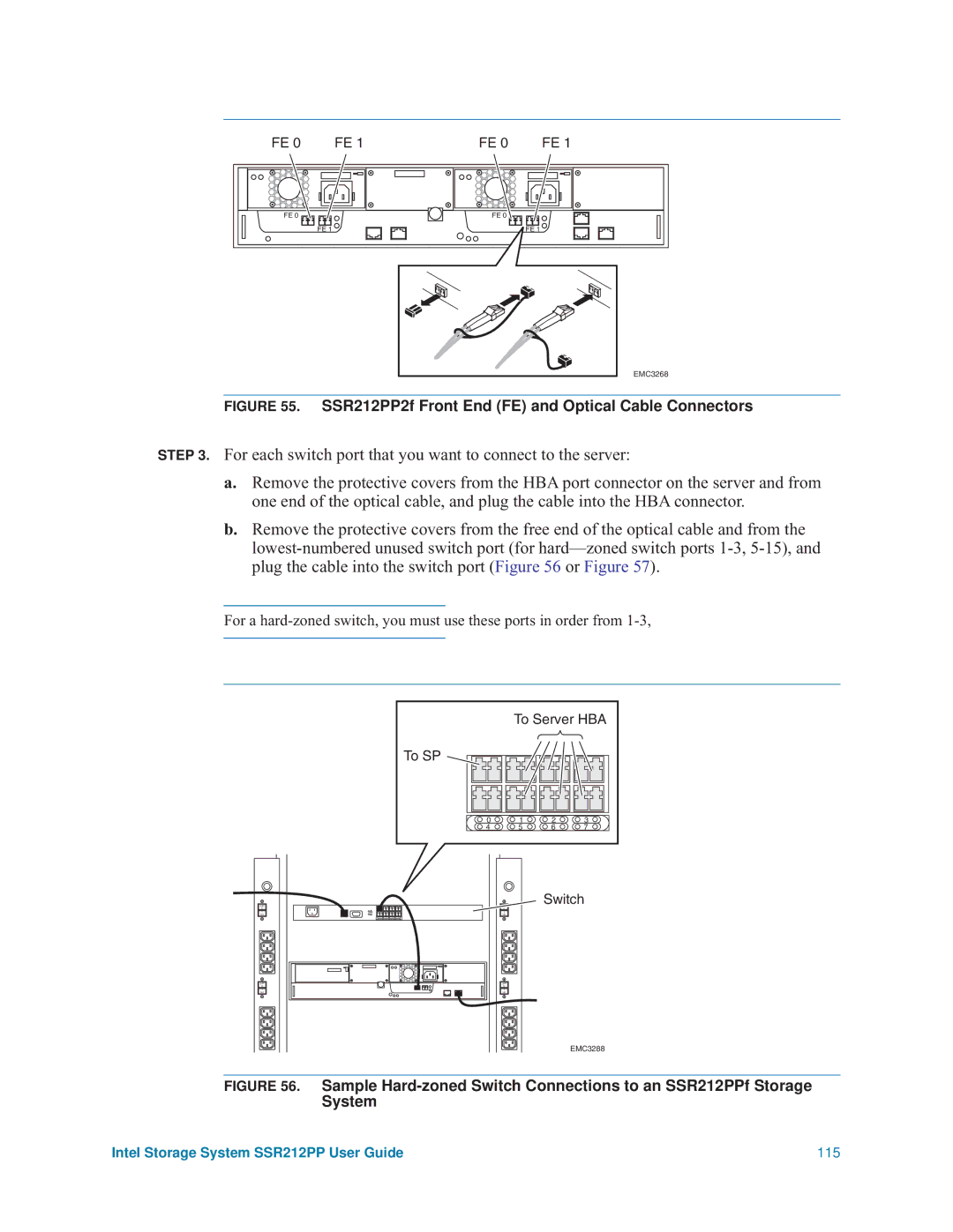
SSR212PP2f Front End FE and Optical Cable Connectors
If the switch is not already powered up, power it up
Intel Storage System SSR212PP User Guide 117
Connecting iSCSI Ports to the Server
Connecting SSR212PPi iSCSI Ports Directly to a Server
LAN
120
Configuring Linux NIC Initiators to Connect to iSCSI Targets
Under Discovery Address Category, after the line
For SuSE
Configuring HBA initiators to connect to iSCSI targets
Configuring the iSNS Client on the Storage System
Configuring iSCSI Initiators for a Configuration With iSNS
Configuring NIC initiators on Windows servers for iSNS
On the server, open the Navisphere Server Utility
Dchp
Configuring HBA initiators on Windows servers for iSNS
Running the Navisphere Server Utility on a Windows Server
Select your language, if prompted for it
Click Next to register the server with the storage system
Verifying HBA Registration
Running the Navisphere Server Utility on a Linux Server
Click Finish to exit the utility
On the server, run the utility by entering
Configuring a New Storage System
Where drivermodule is the driver module name
Create one or more virtual disks on each disk pool
Make the virtual disks visible For HBAs
Ii. On the Control Panel, do one of the following
For NICs
For other Windows servers
Configuring an Existing Storage System
134
On Windows 2003 Server hosts
136
Setting up Chap Security for iSCSI Storage Systems
On a Windows server without iSNS log off and remove targets
Removing iSCSI Targets
To set basic security, click Basic
Setting Up Basic Initiator Chap on the Storage System
Setting up Advanced Initiator Chap on the Storage System
Under Security, click Basic
To set advanced security, click Advanced
Setting up Mutual Initiator Chap on the Storage System
Configuring Basic Chap on a Windows Server with NICs
ISCSI Security Advanced screen, click Enable
Intel Storage System SSR212PP User Guide 143
Configuring Basic Chap on a Linux Server with NICs
Intel Storage System SSR212PP User Guide 145
# Notes
Intel Storage System SSR212PP User Guide 147
Click Enable for your target IP
Click Config Authentication on the bottom of the pane
Configuring Basic Chap on a Server with iSCSI HBAs
Select the Chap tab
Click Finish in the success window
150
Select the Target Settings tab
Username=john Password=welcome
Adding NIC or iSCSI HBA Initiators to the Chap Configuration
Setting up advanced initiator Chap on the storage system
154
On the server, enter
Preparing Virtual Disks for Linux
For each virtual disk On the server enter
Create a file system
This command creates the powermt.ctm configuration file
Save the server s PowerPath configuration
Preparing Virtual Disks for Windows
This command creates the powermt.custom configuration file
Verifying the Failover Configuration
Verify the paths to the disk to which you are writing data
Verifying the Failover Configuration for a Windows Server
Verifying the Failover Configuration for a Linux Server
Running Navisphere Express
164
On a Windows Server
On Linux
166
Select Reboot both SPs
Applying iSCSI Data Port Addresses to the SP Assembly
168
Restoring a Storage Processor Boot Image
Shows a cable connection between a COM port and SP a
Restoring an SP Boot Image
To start a HyperTerminal session, follow this path
Connecting a Server or Laptop COM Port to an SP Service Port
172
Screen Shot Interrupting the Alphabetic Test
Press Enter to continue to the Main Menu Figure
Screen Shot Booting from the Utilities Partition
Screen Shot Toolkit Main Menu
Screen Shot Select Images to Install
Screen Shot Copying the Boot Image
178
Using FTP to Obtain and Store an SP Boot Image
Enter n. The software displays the Toolkit Screen Main Menu
Screen Shot Confirm LAN Service Port Configuration
Clariion
182