ProSafe Premium 3 x 3
Rear Panel
|
|
|
|
|
|
|
|
|
|
|
|
|
|
|
|
|
|
|
|
|
|
|
|
|
|
|
|
1 | 2 | 3 | 4 |
|
|
|
| 7 |
|
| |||
| 5 | 6 | 8 | ||||||||||
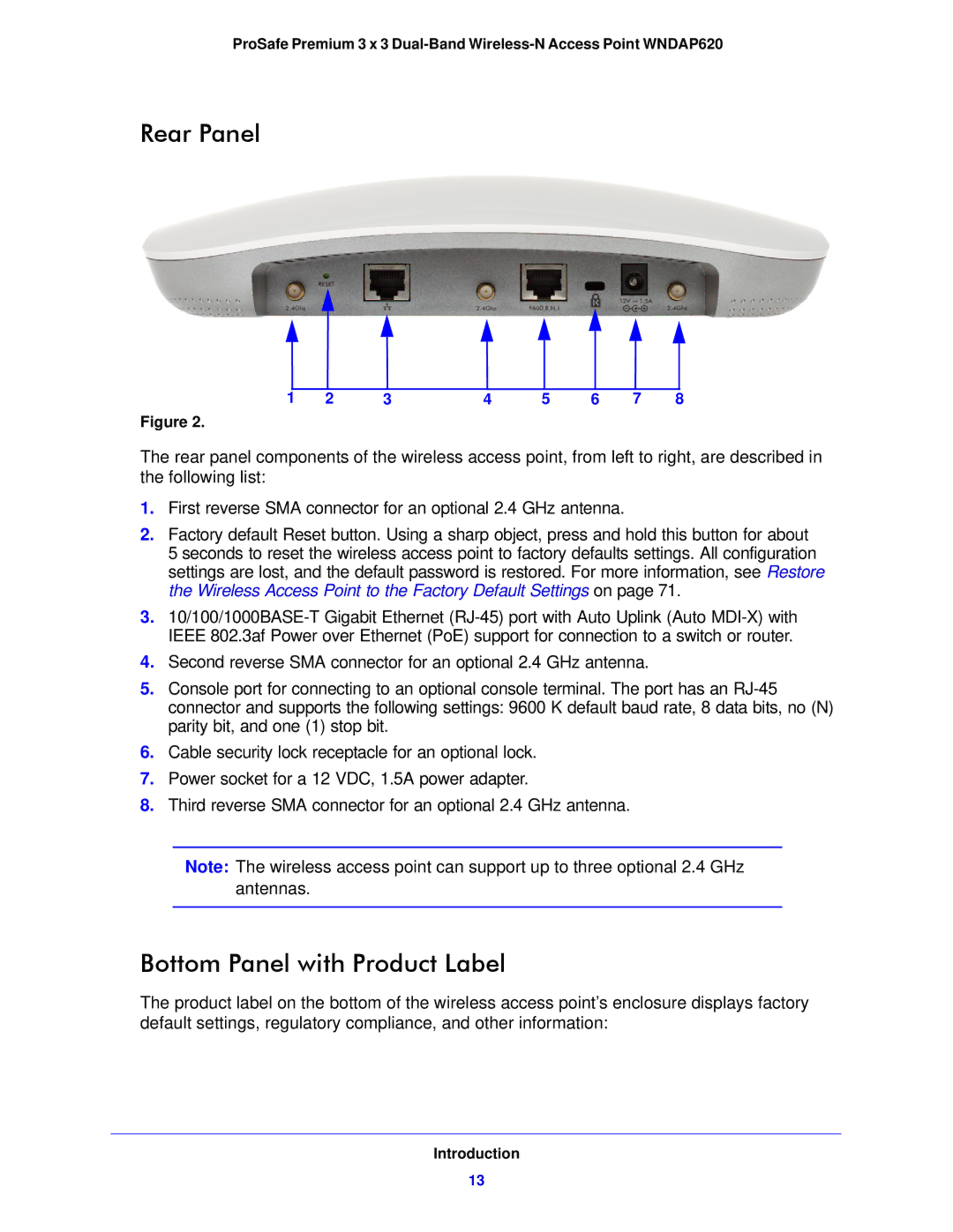
Figure 2.
The rear panel components of the wireless access point, from left to right, are described in the following list:
1.First reverse SMA connector for an optional 2.4 GHz antenna.
2.Factory default Reset button. Using a sharp object, press and hold this button for about
5 seconds to reset the wireless access point to factory defaults settings. All configuration settings are lost, and the default password is restored. For more information, see Restore the Wireless Access Point to the Factory Default Settings on page 71.
3.
4.Second reverse SMA connector for an optional 2.4 GHz antenna.
5.Console port for connecting to an optional console terminal. The port has an
6.Cable security lock receptacle for an optional lock.
7.Power socket for a 12 VDC, 1.5A power adapter.
8.Third reverse SMA connector for an optional 2.4 GHz antenna.
Note: The wireless access point can support up to three optional 2.4 GHz antennas.
Bottom Panel with Product Label
The product label on the bottom of the wireless access point’s enclosure displays factory default settings, regulatory compliance, and other information:
Introduction
13