Part No. 209418-A May 4401 Great America Parkway Santa Clara, CA
Using the BayStack 420 10/100/1000 Switch
Trademarks
Copyright 2001 Nortel Networks
Restricted rights legend
Statement of conditions
Taiwan Requirements
Japan/Nippon Requirements Only
Canada Requirements Only
Using the BayStack 420 10/100/1000 Switch
209418-A
Nortel Networks Inc. software license agreement
own data and information and for maintaining adequate procedures apart from the Software to reconstruct lost or altered files, data, or programs
Using the BayStack 420 10/100/1000 Switch
209418-A
Chapter BayStack 420 Switch
Contents
Preface
Using the BayStack 420 10/100/1000 Switch
8 Contents
Chapter Network configuration
209418-A
Chapter
Using the console interface
Appendix A Technical specifications
Chapter Troubleshooting
10 Contents
209418-A
Appendix C Quick configuration for MultiLink Trunking Appendix D
Appendix B Installing a Gigabit Interface Converter GBIC
Connectors and pin assignments
Appendix E Default settings Appendix F
209418-A
12 Contents
Using the BayStack 420 10/100 Ethernet Switch
Figures
209418-A
14 Figures
Figures
209418-A
16 Figures
Tables
Physical dimensions
Environmental specifications
Performance specifications
GBIC specifications
Before you begin
Preface
where there is more than one option. You must choose
Text conventions
ethernet/2/1 and as many parameter-value pairs as
show at validroute
italic text
show ip alerts routes, you enter either
show ip alerts or show ip routes, but not both
Related publications
Technical Solutions Center
How to get help
Telephone
209418-A
24 Preface
“Physical description,” next “Features” on page
Chapter BayStack 420 Switch
Physical description
Chapter 1 BayStack 420 Switch
Console port
Front panel
Gigabit Interface Converter GBIC
Port connectors
LED display panel
BayStack 420-24T Switch
Table 2 BayStack 420 Switch LED descriptions
Chapter 1 BayStack 420 Switch
Using the BayStack 420 10/100/1000 Switch
Label
Back panel
Cascade Up and Down connectors
Cooling fans
Specifications
AC power receptacle
Country/Plug description
Typical plug
Vorsicht Bitte sofort lesen
Caution Please read immediately
Attention Lisez ceci immédiatement
Attenzione Leggere attentamente
Advertencia Sírvase leer inmediatamente
Virtual Local Area Networks VLANs
Features
Student Dormitory
Security
Teachers’ offices
and classrooms
The switch
MAC address-based security
RADIUS-based network security
Configuration parameters storage
Switch software image storage
Flash memory storage
Port mirroring conversation steering
MultiLink Trunking
Autosensing, autonegotiation, and autopolarity
Standards
RFCs
Application
SNMP MIB support
Standard MIBs
Proprietary MIBs
Appendix F, “Sample BootP configuration file,” on page
BootP automatic IP configuration/MAC address
SNMP trap support
Configuration and switch management
Optivity network management software consists of views, most of which are maps that illustrate the interconnections between the segments, rings, and nodes of your network. The views allow you to analyze network performance and fault conditions on the individual segments and specific areas in your network. They can also alert you when a problem has occurred in a specific location. For further information about Optivity, contact your Nortel Networks sales representative
Network configuration examples
Chapter Network configuration
Desktop switch application
“Network configuration examples,” next
Before
Segment switch application
After
Figure 7 BayStack 420 Switch used as a segment switch
Chapter 2 Network configuration
Using the BayStack 420 10/100/1000 Switch
9997EA
High-density switched workgroup application
Unit Select switch
BayStack 420 Switch stack operation
9998EB
Base unit
Initial installation
Stack MAC address
Stack up configurations
Stack configurations
Removing a unit from the stack
Stack down configurations
10002EA
In Unit Unit Unit Unit Unit Unit Unit Unit
IEEE 802.1Q VLAN workgroups
VLAN BayStack
IEEE 802.1Q tagging
VLAN
Untagged member-a port that has been configured as an untagged member of a specific VLAN. When an untagged frame exits the switch through an untagged member port, the frame header remains unchanged. When a tagged frame exits the switch through an untagged member port, the tag is stripped and the tagged frame is changed to an untagged frame
BS45010A
3 bits
16 bits
1 bits
12 bits
BS45014A
BS45013A
Port
VLANs spanning multiple 802.1Q tagged switches
VLANs spanning multiple switches
tagging switch
VLANS spanning multiple untagged switches
VLAN
10006EA
10007EA
Shared servers
Ports 8, 6, and 11 are untagged members of VLAN
To configure the VLAN port membership for VLAN
To configure the PVID port VLAN identifier for port
Figure 24 Default VLAN Port Configuration screen example
Chapter 2 Network configuration
Using the BayStack 420 10/100/1000 Switch
The PVID/VLAN association for VLAN 3 is now PVID =
VLAN workgroup summary
Figure 26 VLAN configuration spanning multiple switches
Chapter 2 Network configuration
Using the BayStack 420 10/100/1000 Switch
Untagged ports
MultiLink Trunks
VLAN configuration rules
10009EA
10010EA
Client/server configuration using MultiLink Trunks
BayStack
Trunk configuration screen examples
Trunk configuration screen for Switch S1
Switch S1 is configured as follows
Trunk configuration screen for Switch S2
Figure 32 shows the MultiLink Trunk Configuration screen for Switch S2
78 Chapter 2 Network configuration
Trunk Configuration screen for Switch S3
Figure 33 MultiLink Trunk Configuration screen for Switch S3
209418-A
Trunk Configuration screen for Switch S4
Figure 34 shows the MultiLink Trunk Configuration screen for Switch S4
Before you configure trunks
10013EA
Spanning tree considerations for MultiLink Trunks
10014EA
Figure 37 Example 2 detecting a misconfigured port
84 Chapter 2 Network configuration
209418-A
10017EA
Port mirroring
Additional tips about the MultiLink Trunking feature
Is your port mirroring configuration complete?
Accessing the CI menus and screens
Chapter Using the console interface
“Accessing the CI menus and screens,” next
“Using the CI menus and screens” on page “Main menu” on page
Navigating the CI menus and screens
Using the CI menus and screens
Chapter 3 Using the console interface
Screen fields and descriptions
Using the BayStack 420 10/100/1000 Switch
To return to the previous menu, press Ctrl-R
Main menu
Using the BayStack 420 10/100/1000 Switch
Chapter 3 Using the console interface
Table 9 describes the CI main menu options
Figure 40 Console interface main menu
Port Configuration screen” on page 147. This screen allows you to configure
92 Chapter 3 Using the console interface
Table 9 Console interface main menu options continued
209418-A
Using the BayStack 420 10/100/1000 Switch
Chapter 3 Using the console interface
Table 9 Console interface main menu options continued
IP Configuration/Setup screen
Table 10 IP Configuration/Setup screen fields
Chapter 3 Using the console interface
Using the BayStack 420 10/100/1000 Switch
Choosing a BootP request mode
BootP Always
BootP When Needed
Chapter 3 Using the console interface
Using the BayStack 420 10/100/1000 Switch
BootP or Last Address
BootP Disabled
98 Chapter 3 Using the console interface
209418-A
SNMP Configuration screen
To open the System Characteristics screen
System Characteristics screen
Choose System Characteristics or press s from the main menu
100 Chapter 3 Using the console interface
Chapter 3 Using the console interface
Table 12 describes the System Characteristics screen fields
Figure 43 System Characteristics screen
Table 12 System Characteristics screen fields
Table 12 System Characteristics screen fields continued
102 Chapter 3 Using the console interface
A read-only field that shows the length of time since the last reset. Note that this field
209418-A
Switch Configuration Menu screen
104 Chapter 3 Using the console interface
Table 13 describes the Switch Configuration Menu options
Table 13 Switch Configuration Menu options
209418-A
See “System Log screen” on page
MAC Address Table screen
Table 14 describes the MAC Address Table screen fields
106 Chapter 3 Using the console interface
Figure 45 MAC Address Table screen
Table 14 MAC Address Table screen fields
MAC Address Security Configuration Menu screen
Address Security Port Configuration screen” on page 111”. This screen
describes the MAC Address Security Configuration Menu options.” on
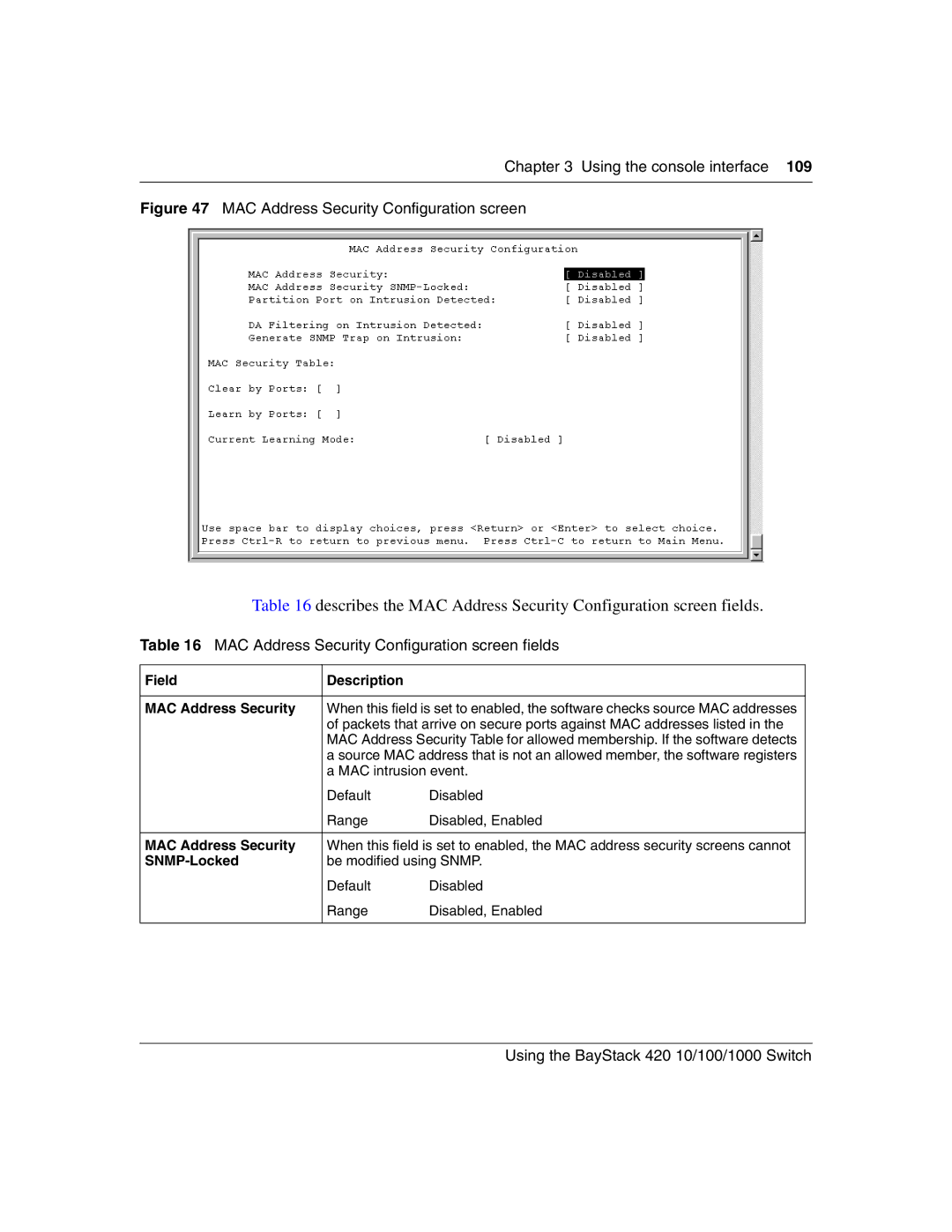
Figure 47 MAC Address Security Configuration screen
Chapter 3 Using the console interface
Table 16 MAC Address Security Configuration screen fields
Using the BayStack 420 10/100/1000 Switch
Table 16 MAC Address Security Configuration screen fields continued
110 Chapter 3 Using the console interface
Configuration screen see “Port Configuration screen” on page
“SNMP Configuration screen” on page
MAC Address Security Port Configuration screen
Figure 48 MAC Security Port Configuration screen 1 of
112 Chapter 3 Using the console interface
Figure 49 MAC Security Port Configuration screen 2 of
209418-A
MAC Address Security Port Lists screens
To open the MAC Address Security Lists screen
Port list syntax
Adding a new port to an existing port number list
Accelerator keys for repetitive tasks
Copying an existing field into and adjacent field
Removing a port from an existing port number list
MAC Address Security Table screens
Using the BayStack 420 10/100/1000 Switch
Chapter 3 Using the console interface
Table 19 describes the MAC Address Security Table screen fields
Figure 53 MAC Address Security Table screen
A single unit/port or a port list value for example, 1/3, 1/6
VLAN Configuration Menu screen
Figure 54 VLAN Configuration Menu screen
Chapter 3 Using the console interface
Table 20 VLAN Configuration Menu options
Using the BayStack 420 10/100/1000 Switch
VLAN Configuration screen
Chapter 3 Using the console interface
Table 21 describes the VLAN Configuration screen fields
Figure 55 VLAN Configuration screen
Table 21 VLAN Configuration screen fields
Table 21 VLAN Configuration screen fields continued
124 Chapter 3 Using the console interface
209418-A
VLAN # VLAN number
VLAN Port Configuration screen
126 Chapter 3 Using the console interface
Table 22 describes the VLAN Port Configuration screen fields
Figure 56 VLAN Port Configuration screen
Table 22 VLAN Port Configuration screen fields
VLAN Display by Port screen
Table 23 describes the VLAN Display by Port screen fields
128 Chapter 3 Using the console interface
Figure 57 VLAN Display by Port screen
Table 23 VLAN Display by Port screen fields
Port Configuration screen
130 Chapter 3 Using the console interface
Table 24 describes the Port Configuration screen fields
Figure 59 Port Configuration screen 2 of
Table 24 Port Configuration screen fields
High Speed Flow Control Configuration screen
Figure 60 High Speed Flow Control Configuration
132 Chapter 3 Using the console interface
Table 25 High Speed Flow Control Configuration screen fields
209418-A
Choosing a high speed flow control mode
MultiLink Trunk Configuration Menu screen
Symmetric mode
Asymmetric mode
To open the MultiLink Trunk Configuration Menu screen
MultiLink Trunk Configuration screen
136 Chapter 3 Using the console interface
Table 27 describes the MultiLink Trunk Configuration screen fields
Figure 62 MultiLink Trunk Configuration screen
Table 27 MultiLink Trunk Configuration screen fields
MultiLink Trunk Utilization screen
Figure 63 MultiLink Trunk Utilization screen 1 of
138 Chapter 3 Using the console interface
Figure 64 MultiLink Trunk Utilization screen 2 of
209418-A
Figure 65 shows an example of a Port Mirroring Configuration screen
Port Mirroring Configuration screen
Chapter 3 Using the console interface
Using the BayStack 420 10/100/1000 Switch
Figure 65 Port Mirroring Configuration screen
140 Chapter 3 Using the console interface
Table 29 Port Mirroring Configuration screen fields
209418-A
Port Statistics screen
To open the Port Statistics screen
Using the BayStack 420 10/100/1000 Switch
Chapter 3 Using the console interface
Only appears if the switch is participating in a stack configuration. The field allows
Table 31 Port Statistics screen fields
Table 31 Port Statistics screen fields continued
144 Chapter 3 Using the console interface
209418-A
Transmitted column Indicates the total number of 1024-byte to 1518-byte packets
System Log screen
Table 32 describes the System Log screen fields
146 Chapter 3 Using the console interface Figure 67 System Log screen
Table 32 System Log screen fields
209418-A
Console/Comm Port Configuration screen
148 Chapter 3 Using the console interface
Table 33 describes the Console/Comm Port Configuration screen fields
Figure 68 Console/Comm Port Configuration screen
Table 33 Console/Comm Port Configuration screen fields
Table 33 Console/Comm Port Configuration screen fields continued
Chapter 3 Using the console interface
Using the BayStack 420 10/100/1000 Switch
None, Local Password, RADIUS Authentication
Table 33 Console/Comm Port Configuration screen fields continued
150 Chapter 3 Using the console interface
participating switch in a stack configuration through a console terminal
209418-A
Table 33 Console/Comm Port Configuration screen fields continued
Chapter 3 Using the console interface
Using the BayStack 420 10/100/1000 Switch
Any ASCII string of up to 15 printable characters
Table 33 Console/Comm Port Configuration screen fields continued
152 Chapter 3 Using the console interface
Caution you change the system-supplied default passwords, be sure to
209418-A
Table 33 Console/Comm Port Configuration screen fields continued
Chapter 3 Using the console interface
Using the BayStack 420 10/100/1000 Switch
Field
Renumber Stack Units screen
Chapter 3 Using the console interface
Hardware Unit Information screen
Using the BayStack 420 10/100/1000 Switch
Table 34 describes the Renumber Stack Units screen fields
Spanning Tree Configuration Menu screen
Chapter 3 Using the console interface
Table 35 describes the Spanning Tree Configuration Menu options
Figure 71 Spanning Tree Configuration Menu screen
Table 35 Spanning Tree Configuration Menu options
Spanning Tree Port Configuration screen
Chapter 3 Using the console interface
Table 36 describes the Spanning Tree Port Configuration screen fields
Figure 73 Spanning Tree Port Configuration screen 2 of
Table 36 Spanning Tree Port Configuration screen fields
Table 36 Spanning Tree Port Configuration screen fields continued
160 Chapter 3 Using the console interface
When an individual port is a trunk member see Trunk field, changing this setting for one
209418-A
Spanning Tree Switch Settings screen
162 Chapter 3 Using the console interface
Table 37 describes the Spanning Tree Switch Settings parameters
Table 37 Spanning Tree Switch Settings parameters
209418-A
Table 37 Spanning Tree Switch Settings parameters continued
Chapter 3 Using the console interface
Using the BayStack 420 10/100/1000 Switch
Indicates the Forward Delay parameter value that the root bridge is currently using. This
TELNET Configuration screen
Chapter 3 Using the console interface
Table 38 describes the TELNET Configuration screen fields
Table 38 TELNET Configuration screen fields
Using the BayStack 420 10/100/1000 Switch
Software Download screen
To open the Software Download screen
Figure 76 Software Download screen for a BayStack 420 Switch stack
168 Chapter 3 Using the console interface
Table 39 describes the Software Download screen fields
Table 39 Software Download screen fields
LED Indications during the download process
Configuration File Download/Upload screen
To open the Configuration File Download/Upload screen
Table 40 Configuration File Download/Upload screen fields
Chapter 3 Using the console interface
Using the BayStack 420 10/100/1000 Switch
Requirements
“Diagnosing and correcting problems” on page
Chapter Troubleshooting
Interpreting the LEDs
“Interpreting the LEDs,” next
174 Chapter 4 Troubleshooting Figure 78 LED display panel
BayStack 420-24T Switch
Table 42 BayStack 420 Switch LED descriptions
209418-A
Diagnosing and correcting problems
Normal power-up sequence
Autonegotiation modes
Port connection problems
Port interface
Environmental
Appendix A Technical specifications
Electrical
Performance specifications
Physical dimensions
180 Appendix A Technical specifications
Physical dimensions
Network protocol and standards compatibility
Safety agency certification
Electromagnetic emissions
The BayStack 420 Switch meets the EN50082-11997 standard
Electromagnetic immunity
182 Appendix A Technical specifications
209418-A
Product description
Appendix B Installing a Gigabit Interface Converter GBIC
9702FA
GBIC labeling
9706EA
GBIC specifications
Standards, connectors, cabling, and distance
GBIC Models
1000BASE-SX
1000BASE-LX
SC-SC Mode Conditioning Patch Cord 62.5/125-part number AA0018035
1000BASE-XD
1000BASE-ZX
Handling, safety, and environmental guidelines
8769EA
Installing a GBIC
To install a GBIC 1 Remove the GBIC from its protective packaging
Appendix C Quick configuration for MultiLink Trunking
Figure 83 Configuring MultiLink Trunks
194 Appendix C Quick configuration for MultiLink Trunking
Configure trunk members see MultiLink Trunking Configuration Rules
Configuration Rules
RJ-45 10BASE-T/100BASE-TX port connectors
Appendix D Connectors and pin assignments
MDI and MDI-X devices
MDI-X to MDI-X cable connections
MDI-X to MDI cable connections
BayStack 420 Switch
DB-9 RS-232-D Console/Comm Port connector
Switch or hub
Appendix D Connectors and pin assignments
Table 55 lists the DB-9 Console port connector pin assignments
Table 55 DB-9 Console port connector pin assignments
Using the BayStack 420 10/100/1000 Switch
209418-A
200 Appendix D Connectors and pin assignments
Table 56 Factory default settings
Appendix E Default settings
Using the BayStack 420 10/100/1000 Switch
Table 56 Factory default settings continued
202 Appendix E Default settings
Default setting
209418-A
Table 56 Factory default settings continued
Appendix E Default settings
Using the BayStack 420 10/100/1000 Switch
Default setting
Table 56 Factory default settings continued
204 Appendix E Default settings
Default setting
209418-A
Table 56 Factory default settings continued
Appendix E Default settings
Using the BayStack 420 10/100/1000 Switch
Retrieve Configuration Image from
209418-A
206 Appendix E Default settings
Appendix F Sample BootP configuration file
209418-A
208 Appendix F Sample BootP configuration file
Index
Page
Index
Using the BayStack 420 10/100/1000 Switch
209418-A
212 Index