Chapter 2 Network configuration 73
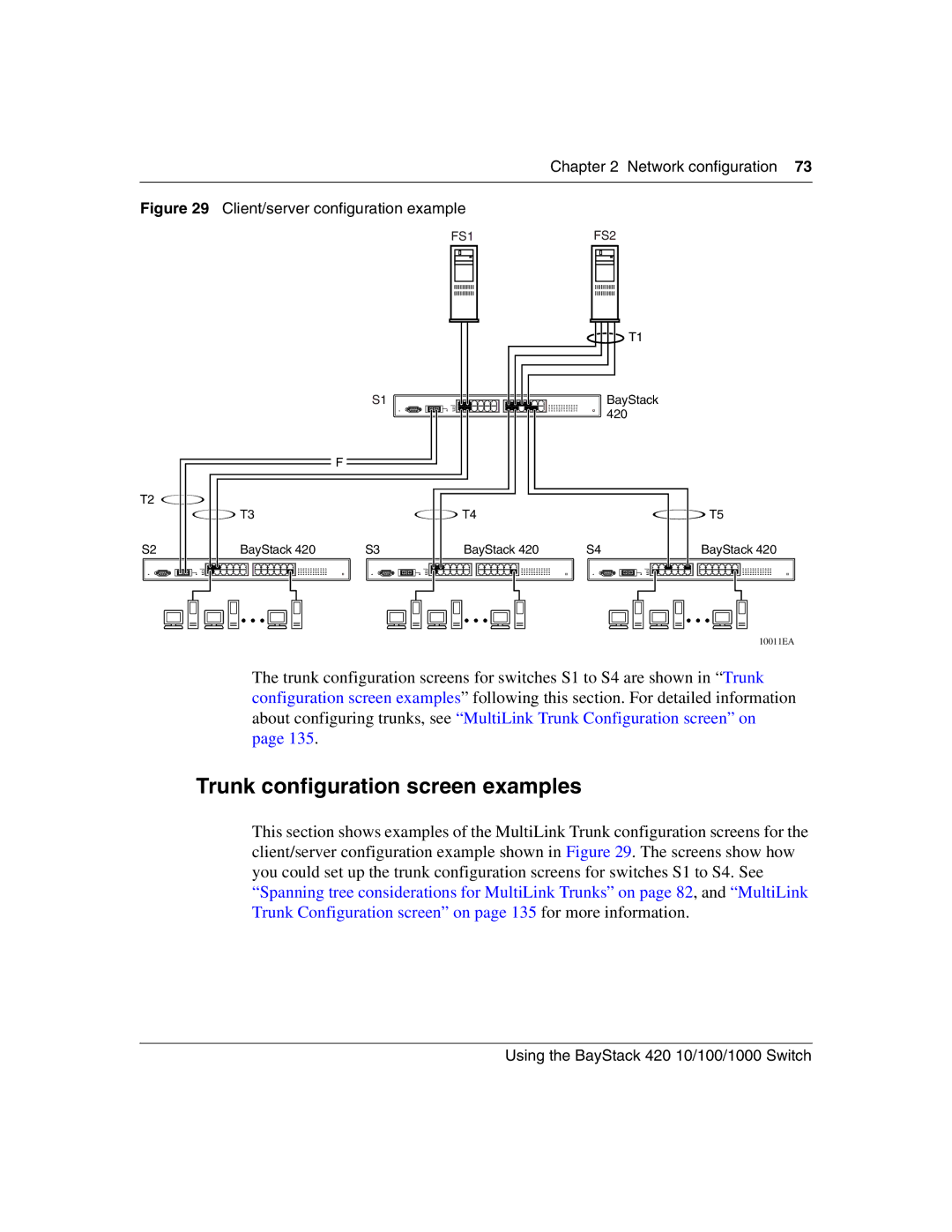
Figure 29 Client/server configuration example
FS1 |
|
| S1 |
|
|
| F |
|
T2 |
|
|
|
| T3 |
| T4 |
S2 | BayStack 420 | S3 | BayStack 420 |
FS2 |
T1 |
BayStack 420
![]() T5
T5
S4 | BayStack 420 | |||||||||||||||
|
|
|
|
|
|
|
|
|
|
|
|
|
|
|
|
|
|
|
|
|
|
|
|
|
|
|
|
|
|
|
|
|
|
|
|
|
|
|
|
|
|
|
|
|
|
|
|
|
|
|
|
|
|
|
|
|
|
|
|
|
|
|
|
|
|
|
|
|
|
|
|
|
|
|
|
|
|
|
|
|
|
|
|
|
|
|
|
|
|
|
|
|
|
|
|
|
|
|
|
|
|
10011EA
The trunk configuration screens for switches S1 to S4 are shown in “Trunk configuration screen examples” following this section. For detailed information about configuring trunks, see “MultiLink Trunk Configuration screen” on page 135.
Trunk configuration screen examples
This section shows examples of the MultiLink Trunk configuration screens for the client/server configuration example shown in Figure 29. The screens show how you could set up the trunk configuration screens for switches S1 to S4. See “Spanning tree considerations for MultiLink Trunks” on page 82, and “MultiLink Trunk Configuration screen” on page 135 for more information.