130Chapter 3 Using the console interface
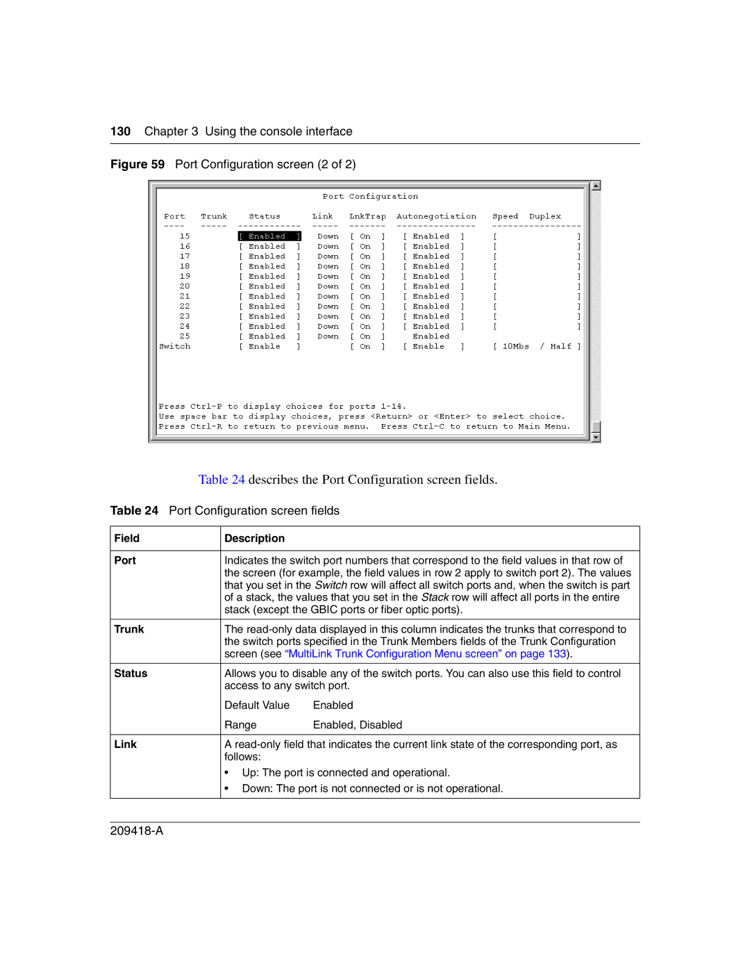
Figure 59 Port Configuration screen (2 of 2)
Table 24 describes the Port Configuration screen fields.
Table 24 Port Configuration screen fields
Field | Description |
|
|
| |
Port | Indicates the switch port numbers that correspond to the field values in that row of | |
| the screen (for example, the field values in row 2 apply to switch port 2). The values | |
| that you set in the Switch row will affect all switch ports and, when the switch is part | |
| of a stack, the values that you set in the Stack row will affect all ports in the entire | |
| stack (except the GBIC ports or fiber optic ports). | |
|
| |
Trunk | The | |
| the switch ports specified in the Trunk Members fields of the Trunk Configuration | |
| screen (see “MultiLink Trunk Configuration Menu screen” on page 133). | |
|
| |
Status | Allows you to disable any of the switch ports. You can also use this field to control | |
| access to any switch port. | |
| Default Value | Enabled |
| Range | Enabled, Disabled |
|
| |
Link | A | |
| follows: |
|
| • Up: The port is connected and operational. | |
| • Down: The port is not connected or is not operational. | |
|
|
|