26 Chapter 1 BayStack 420 Switch
Front panel
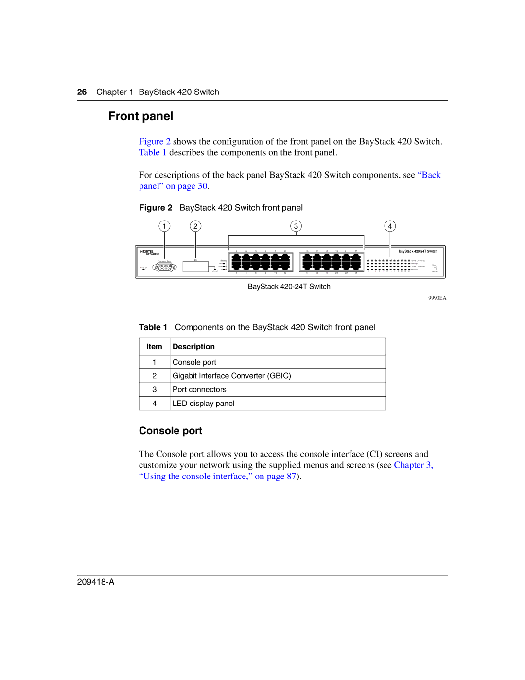
Figure 2 shows the configuration of the front panel on the BayStack 420 Switch. Table 1 describes the components on the front panel.
For descriptions of the back panel BayStack 420 Switch components, see “Back panel” on page 30.
Figure 2 BayStack 420 Switch front panel
1 | 2 | 3 | 4 |
Console Port
Power On
|
|
|
|
|
|
| 1 | 3 | 5 | 7 | 9 | 11 |
|
|
|
|
|
|
| ||||||
|
|
| ||||||||||
|
|
|
|
|
|
|
|
|
|
|
|
|
25 |
| Cascade |
|
|
|
|
|
| ||||
|
|
|
|
|
|
|
|
|
|
|
| |
|
|
| Base |
|
|
|
|
|
|
|
| |
|
|
| Down |
|
|
|
|
|
|
| ||
|
|
|
|
|
|
|
|
|
|
| ||
|
|
|
| Up |
|
|
|
|
|
|
| |
|
| Link/Act |
|
|
|
|
|
| ||||
|
|
| 2 | 4 | 6 | 8 | 10 | 12 | ||||
13 | 15 | 17 | 19 | 21 | 23 |
|
|
|
|
|
|
|
|
|
| BayStack | ||||
|
|
|
|
|
|
|
|
|
| |||||||||||
|
|
|
|
|
|
|
|
|
| |||||||||||
|
|
|
|
|
|
| 1 | 3 | 5 | 7 | 9 | 11 | 13 | 15 | 17 | 19 | 21 | 23 | 10/100 Link Activity | |
|
|
|
|
|
|
|
|
|
|
|
|
|
|
|
|
|
|
|
| |
|
|
|
|
|
|
|
|
|
|
|
|
|
|
|
|
|
|
|
| HDX/FDX |
|
|
|
|
|
|
|
|
|
|
|
|
|
|
|
|
|
|
|
| Base |
|
|
|
|
|
|
|
|
|
|
|
|
|
|
|
|
|
|
|
| 10/100 Link Activity |
|
|
|
|
|
|
| 2 | 4 | 6 | 8 | 10 | 12 | 14 | 16 | 18 | 20 | 22 | 24 | HDX/FDX | |
|
|
|
|
|
|
| Unit Set | |||||||||||||
14 | 16 | 18 | 20 | 22 | 24 |
| ||||||||||||||
|
|
|
|
|
|
|
|
|
|
|
|
|
|
| ||||||
BayStack
9990EA
Table 1 Components on the BayStack 420 Switch front panel
Item | Description |
|
|
1 | Console port |
|
|
2 | Gigabit Interface Converter (GBIC) |
|
|
3 | Port connectors |
|
|
4 | LED display panel |
|
|
Console port
The Console port allows you to access the console interface (CI) screens and customize your network using the supplied menus and screens (see Chapter 3, “Using the console interface,” on page 87).