Chapter 2 Network configuration 57
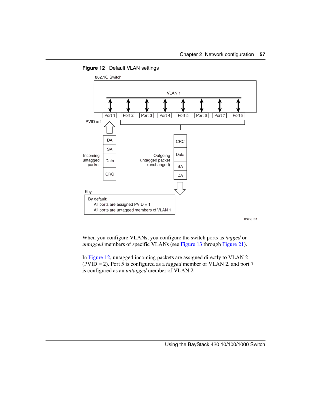
Figure 12 Default VLAN settings
802.1Q Switch
|
|
| VLAN 1 |
|
|
| |
Port 1 | Port 2 | Port 3 | Port 4 | Port 5 | Port 6 | Port 7 | Port 8 |
PVID = 1 |
|
|
|
|
|
|
|
DA
SA
Incoming
untagged Data packet
CRC
Key
CRC
Outgoing Data untagged packet
(unchanged) SA
DA
By default:
All ports are assigned PVID = 1
All ports are untagged members of VLAN 1
BS45010A
When you configure VLANs, you configure the switch ports as tagged or untagged members of specific VLANs (see Figure 13 through Figure 21).
In Figure 12, untagged incoming packets are assigned directly to VLAN 2 (PVID = 2). Port 5 is configured as a tagged member of VLAN 2, and port 7 is configured as an untagged member of VLAN 2.