136Chapter 3 Using the console interface
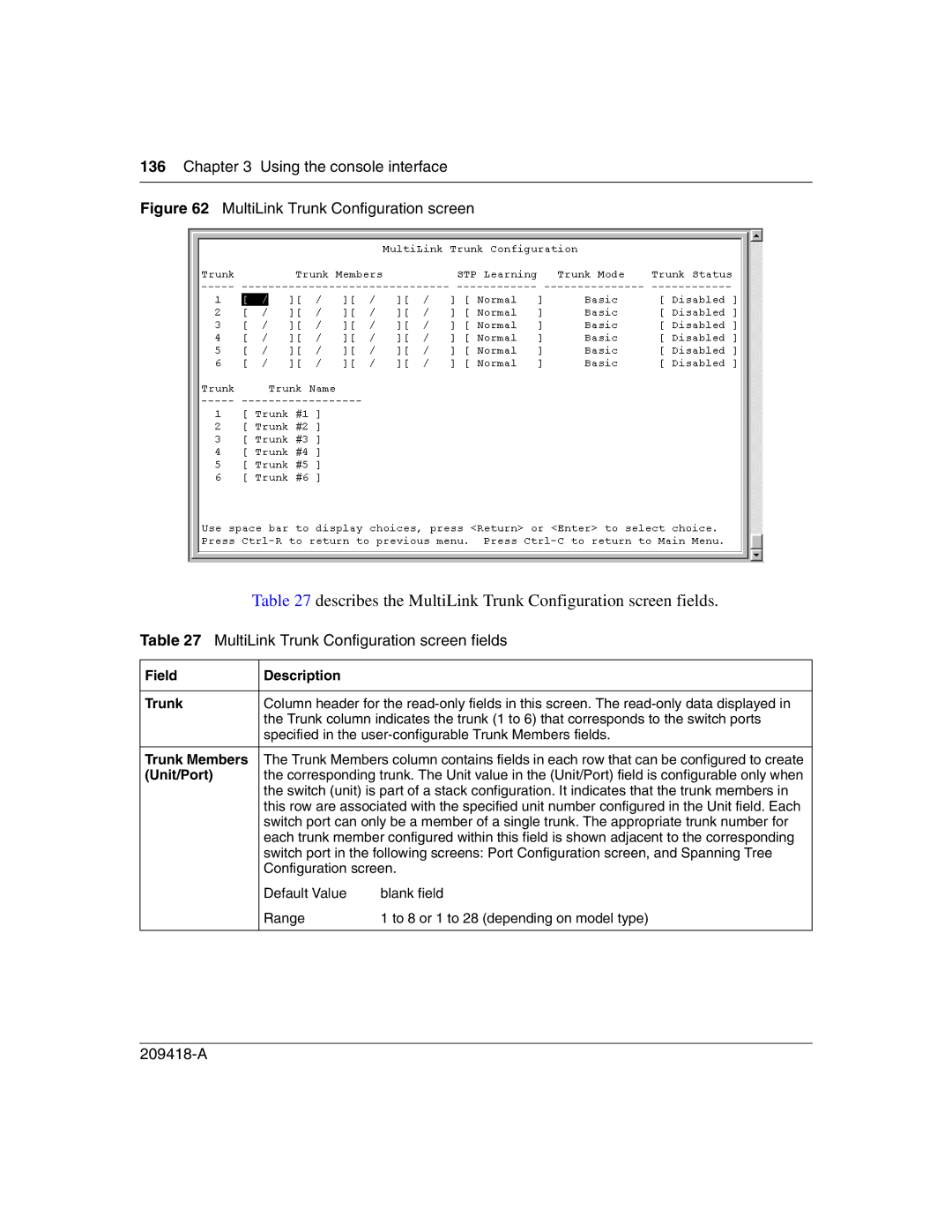
Figure 62 MultiLink Trunk Configuration screen
Table 27 describes the MultiLink Trunk Configuration screen fields.
Table 27 MultiLink Trunk Configuration screen fields
Field | Description |
|
|
| |
Trunk | Column header for the | |
| the Trunk column indicates the trunk (1 to 6) that corresponds to the switch ports | |
| specified in the | |
|
| |
Trunk Members | The Trunk Members column contains fields in each row that can be configured to create | |
(Unit/Port) | the corresponding trunk. The Unit value in the (Unit/Port) field is configurable only when | |
| the switch (unit) is part of a stack configuration. It indicates that the trunk members in | |
| this row are associated with the specified unit number configured in the Unit field. Each | |
| switch port can only be a member of a single trunk. The appropriate trunk number for | |
| each trunk member configured within this field is shown adjacent to the corresponding | |
| switch port in the following screens: Port Configuration screen, and Spanning Tree | |
| Configuration screen. | |
| Default Value | blank field |
| Range | 1 to 8 or 1 to 28 (depending on model type) |
|
|
|
