30 Chapter 1 BayStack 420 Switch
Back panel
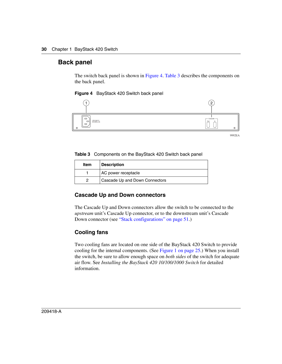
The switch back panel is shown in Figure 4. Table 3 describes the components on the back panel.
Figure 4 BayStack 420 Switch back panel
1 | 2 |
Cascade
Out In
9992EA
Table 3 Components on the BayStack 420 Switch back panel
Item | Description |
1AC power receptacle
2Cascade Up and Down Connectors
Cascade Up and Down connectors
The Cascade Up and Down connectors allow the switch to be connected to the upstream unit’s Cascade Up connector, or to the downstream unit’s Cascade Down connector (see “Stack configurations” on page 51.)
Cooling fans
Two cooling fans are located on one side of the BayStack 420 Switch to provide cooling for the internal components. (See Figure 1 on page 25.) When you install the switch, be sure to allow enough space on both sides of the switch for adequate air flow. See Installing the BayStack 420 10/100/1000 Switch for detailed information.