58 Chapter 2 Network configuration
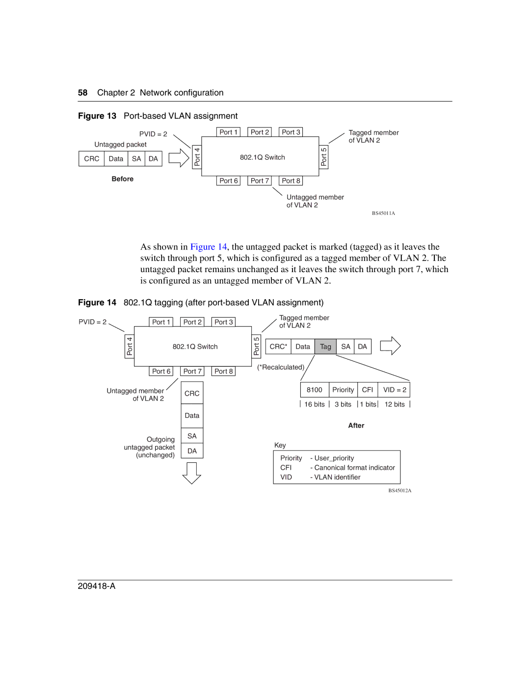
Figure 13 Port-based VLAN assignment
|
| PVID = 2 |
|
| ||
Untagged packet |
|
| ||||
|
|
|
|
| 4 |
|
CRC | Data | SA | DA |
| Port |
|
|
|
| ||||
|
|
|
|
|
|
|
|
|
|
|
|
| |
| Before |
|
| |||
|
|
| ||||
Port 1 |
| Port 2 |
| Port 3 |
| 802.1Q Switch | |||
|
|
|
|
|
Port 6 |
| Port 7 |
| Port 8 |
![]() Port 5
Port 5
Tagged member of VLAN 2
Untagged member of VLAN 2
BS45011A
As shown in Figure 14, the untagged packet is marked (tagged) as it leaves the switch through port 5, which is configured as a tagged member of VLAN 2. The untagged packet remains unchanged as it leaves the switch through port 7, which is configured as an untagged member of VLAN 2.
Figure 14 802.1Q tagging (after port-based VLAN assignment)
PVID = 2
Port 4![]()
Port 1 |
| Port 2 |
| Port 3 |
|
| 802.1Q Switch |
| |||
|
|
|
|
|
|
Port 6 |
| Port 7 |
| Port 8 |
|
Tagged member of VLAN 2
5 |
|
|
|
|
|
|
Port |
| CRC* | Data | Tag | SA | DA |
|
|
|
|
|
| |
|
|
|
|
|
| |
|
|
|
|
|
|
|
(*Recalculated) | ||||||
Untagged member | CRC | |
of VLAN 2 | ||
| ||
| Data |
Outgoing SA
| 8100 |
| Priority |
| CFI |
| VID = 2 |
| |
|
|
|
|
|
|
|
|
|
|
| 16 bits |
| 3 bits |
| 1 bits |
| 12 bits |
|
|
|
|
|
|
| |||||
|
|
| After |
|
|
|
| ||
untagged packet (unchanged)
DA
Key |
|
Priority | - User_priority |
CFI | - Canonical format indicator |
VID | - VLAN identifier |
|
|
BS45012A