62 Chapter 2 Network configuration
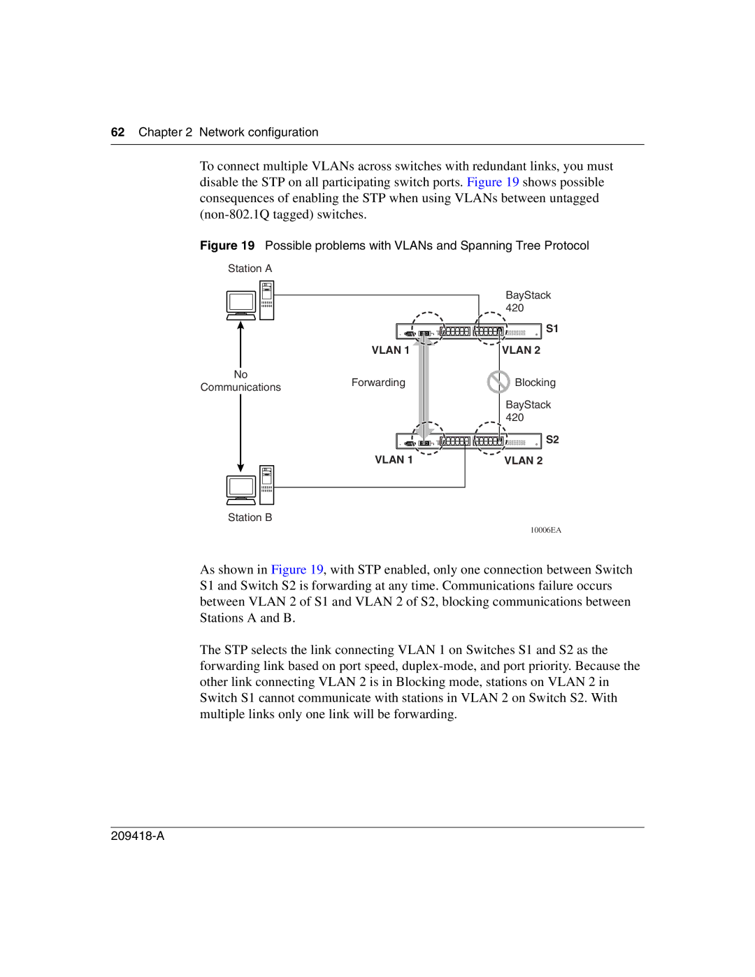
To connect multiple VLANs across switches with redundant links, you must disable the STP on all participating switch ports. Figure 19 shows possible consequences of enabling the STP when using VLANs between untagged
Figure 19 Possible problems with VLANs and Spanning Tree Protocol
Station A
VLAN 1
No
CommunicationsForwarding
VLAN 1
BayStack |
420 |
S1 |
VLAN 2 |
Blocking |
BayStack |
420 |
S2 |
VLAN 2
Station B
10006EA
As shown in Figure 19, with STP enabled, only one connection between Switch S1 and Switch S2 is forwarding at any time. Communications failure occurs between VLAN 2 of S1 and VLAN 2 of S2, blocking communications between Stations A and B.
The STP selects the link connecting VLAN 1 on Switches S1 and S2 as the forwarding link based on port speed,