Isdn Primary Rate Interface Installation and Commissioning
Legal Notice
Contents
Msdl installation for all systems
Clock Controller description and installation 155
Mb DTI implementation 237
Procedures
Copyright 2003-2007, Nortel Networks
Other
New in this release
Revision History
0Mb DTI/PRI Description, Installation and Maintenance
Getting help from the Nortel web site
How to get help
Getting help through a Nortel distributor or reseller
Subject
Introduction
Applicable systems
Related information
Intended audience
System migration
Technical Documents
Isdn Primary Rate Interface equipment overview
Contents
Copyright 2003-2007, Nortel Networks
Primary Rate Interface PRI hardware requirements
Introduction
PRI hardware shown without downloadable PRI and DCH cards
Isdn Signaling Link ISL hardware
Isdn Signaling Link ISL hardware
Channel Handler description
Power requirements
Kbit/s Clear Data Hardware
DCH/PRI interface
NT6D11 DCH faceplate layout
QPC757 DCH
QPC757 faceplate
Current
QPC757 DCH faceplate layout
Heat
Amps Watts BTUs
Msdl faceplate
MSDL/PRI interface
NT6D80 Msdl faceplate layout
Standard PRI cards
NTBK51 Downloadable D-Channel Daughterboard
NT8D72 faceplate
NT8D72 PRI faceplate layout
Carrier interface
Cable requirements
Faceplate Destination Type Description
Tracking mode
Echo canceller interface
QMT21 High Speed Data Module
QPC720 PRI for 1.5/2.0 Mb gateway
Reference clock errors
Free run non-tracking mode
Clock controller primary and secondary tracking
Automatic clock switching
Automatic clock recovery
QPC720 faceplate
Pin female, D-connector
Faceplate destination Type
QPC720 Cable requirements
Miniature bantam jack
QPC720 PRI cables and cable lengths Maximum
Link version 2 protocol
Length
Cable type From Length feet Meters
NT5D97 Dual-port DTI2/PRI2 card
Disk drive hardware
External D-Channel Interface DCH or Msdl
NT5D97 faceplate
DCH/MSDL Receiver Ready control signals RR State Condition
OFF
ENB/DIS
Plastic, ESD protected Card Enable/disable Switch
Enet LEDs
Enable/Disable Switch
Faceplate Function Designator Type Description
Unit 0 Clk Connectors
Trunk Disable DIS LEDs
OOS LEDs
NEA LEDs
Connector J5 TRK
Unit 1 Clk Connectors
Connector J6 DCH
System capacity and performance Physical capacity
NT5D97 DDP2 power requirements Voltage Source Current
Testability and diagnostics
CPU capacity
Without
E1 carrier cables
Cable Name Description Color Pins
NTCK45AA cable pins
Panel
NT8D7217
NT8D7217 cable pins
NTCK78AA cable pins
Reference clock cables
NTCK79AA cable pins
MSDL/DCH cables
For a description on each available option
Cable diagrams
DDP2 cable for systems with an I/O panel
DDP2 cable for systems without an I/O panel
Clock for the NT5D97 Clock operation
Clock Controller primary and secondary tracking
Reference clock errors
Clock Controller options summary CC Option CPU Type
Clock configurations
Connector Clk1 provides a Ref 2 clock source from
Connector Clk0 provides a Ref 1 clock source from
Clock Controller options description Clock Option
DDP2
Clock Controller Option
Clock Controller Option
Clock Controller Option
NT5D12 Dual-port DTI/PRI
Channel and Msdl interface
DCHI/MSDL Receiver Ready control signals RR State Condition
NT5D12 faceplate
NT5D12 faceplate general view
Function Designator Type Description Switch
DDP faceplate detailed view External connectors and LEDs
Plastic, ESD Card Enable/disable switch
Protected
ACT
Port Out of Service LEDs
RED
YEL
Port 0 Clk Connectors
Trunk Port Disable LEDs
ACT LEDs
RED LEDs
Port 1 Clk Connectors
NT5D12 Cable requirements
DDP power requirements Voltage Source Current DDP without
NT5D16AA
Trunk Tip/Ring cables
Cable Name Description Color Pins J5 Pins J2, J3
NT5D16AA cable pins
NTCG03AA, NTCG03AB, NTCG03AC, or NTCG03AD
MSDL/DCHI cables External Dchi cable
External Msdl cable
DDP cable for systems with an I/O panel
Clock
Free run non-tracking mode
Automatic clock recovery
Clock Controller options- summary CC Option CPU Type
To Clock Controller Option 4
Clock Controller options description Clock Option
Clock Controller Option
Clock Controller Option
Clock Controller Option
Clock Controller Option
Install the NT6D11AB, NT6D11AE, NT6D11AF DCH
DCH installation
DIP switch settings
Set up the NT6D11AB, NT6D11AE, NT6D11AF Dchi
NT6D11 DIP switches
Protocol selection
Protocol selection switch settings Switch Setting
Valid switch combinations
Port 0 settings Mode Switch setting
Port 1 settings Mode Emulates Switch setting
NT6D11 DCH with ISL high-speed programming jumper settings
Jumper settings
Port 1 mode selection
Port addressing modes Port 0 Mode selection
NT6D11 DCH with ISL low-speed programming jumper settings
Port 0 mode selection Port Mode Switch Setting
SW2.1 SW2.2 Synchronous, D-channel, standard addressing
Port 1 mode selection Port Mode Switch Setting
Port Address Switch Setting Half Group No Device No S10
Install the NT6D11AB, NT6D11AE, NT6D11AF Dchi
Procedure Install the NT6D11AB, NT6D11AE, NT6D11AF DCH
16-31 32-47 48-63 64-79 80-95 96-111 112-127
Remove the NT6D11AB, NT6D11AE, NT6D11AF DCH
Procedure Remove the NT6D11AB, NT6D11AE, NT6D11AF DCH
Procedure Install the QPC757 Dchi
Install the QPC757 DCH
End
SW3 SW4
Port address switch settings
Off
Channel parameter downloading
Procedure Remove the QPC757 DCH
Remove the QPC757 Dchi
Install NTBK51 Ddch on NT5D97 dual-port DTI2/PRI2 card
NTBK51 Ddch installation and removal
Remove NTBK51 Ddch from NT5D97 dual-port DTI2/PRI2 card
Service Interruption
Install NTBK51 Ddch on NT5D12 dual-port DTI/PRI
Remove NTBK51 Ddch from NT5D12 dual-port DTI/PRI
Install the Msdl
Msdl installation for all systems
Procedure Install the Msdl card
Msdl installation for all systems
O o o o o o o o o o o o o o o o
Msdl card layout Msdl switch settings Port 0-SW4 Port 0-SW8
RS-232-D RS-422-A DTE RS-422-A DCE Port 1-SW3 Port 1-SW7
RS-232-D RS-422-A DTE
Replace the Msdl
Procedure Replace the Msdl card
RS-422-A DCE Port 2-SW2 Port 2-SW6
RS-232-D RS-422-A DTE RS-422-A DCE Port 3-SW1 Port 3-SW5
End
Msdl installation for all systems
PRI circuit pack locations
NT8D72 and QPC720 PRI card installation
Cable requirements
Cable requirements
104 NT8D72 and QPC720 PRI card installation
Cable requirements
106 NT8D72 and QPC720 PRI card installation
Cable requirements
108 NT8D72 and QPC720 PRI card installation
Cable requirements
110 NT8D72 and QPC720 PRI card installation
Cable requirements
112 NT8D72 and QPC720 PRI card installation
QPC720 Multi Group cabling without an echo canceller
Msdl
PRI card
For single-group only
Cable From Des Con
QCAD125
Dchi
Jctr
QCAD110
Msdl QCAD128
QCAD133
QPC720 NT6D80
PRI card Patch Panel RS-232 Echo Cance Ller
For single group only
QPC471 CC-0 CC-1 Clock controller NT8D75xx QPC775 Back-up
QPC47
Cable From Des Con Comments
QCP77
QCAD328
Switch settings
Switch settings
Switch 3 options for PRI with ESF
Half Group
Install NT8D72 and QPC720 PRI cards on Large Systems
NT6D39 CPU/NET
Remove NT8D72 and QPC720 PRI cards from Large Systems
Procedure
Install an additional network shelf
126 NT8D72 and QPC720 PRI card installation
NT5D97 circuit card locations
NT5D97 Dual-port DTI2/PRI2 installation and removal
NT5D97AA/AB loops configuration Loop
Port definitions
DTI2 PRI2
NT5D97AD loops configuration Loop
DIP switch settings for NT5D97AA/AB Card Trunks Port
NT5D97AA/AB DIP switch settings
ENB/DSB
Mounted on the face plate Ring Ground
DIP switches for NT5D97AA/AB
OFF Loop operates in the DTI2 mode
Transmission mode
Line build out
OFF 120 ohm
Receiver impedance
Ring ground switches for NT5D97AA/AB
120 ohm
OFF-Ring line is not grounded
Channel daughterboard address See table For future use
Selections of the NTBK51AA D-channel
ENB/DSB mounted on the face Plate Ring Ground S16
NT5D97AD DIP switch settings
Dpnss Msdl
Dip switches locations for NT5D97AD
Trunk interface switches for NT5D97AD Trunk 0 switches
Ring ground switches for NT5D97AD
Trunk 1 switches for NT5D97AD
Msdl external card
NTBK51AA DCH switches for NT5D97AD Switch number Function
S91-10 For future use S81-10
Switch Setting Dnum LD
Install the NT5D97 DDP2
Procedure Install the NT5D97 on Large Systems
Remove the NT5D97 DDP2
140 NT5D97 Dual-port DTI2/PRI2 installation and removal
Configure the NT5D97 DDP2
Procedure Remove the NT5D97 from Large Systems
142 NT5D97 Dual-port DTI2/PRI2 installation and removal
NT5D12 circuit card locations
NT5D12 Dual-port DTI/PRI card installation
DTI
DTI PRI
General Purpose Switches
NT5D12 switch settings
Trunk interface switches Transmission Mode
On SF
15 dB
Ring ground switches
100
120
OFF Ring line is not grounded
DCH mode and address select switches
OFF Msdl or Dchi card
148 NT5D12 Dual-port DTI/PRI card installation
Switch functional areas on the NT5D12
NT5D12 switch default settings
Install the NT5D12 DDP
Procedure Install the NT5D12 on Large Systems
Remove the NT5D12 DDP
Procedure Remove the NT5D12 DDP
Configure the NT5D12 DDP
154 NT5D12 Dual-port DTI/PRI card installation
Clock Controller description and installation
Need for synchronization
Description
NTRB53 Clock Controller
Supported Clock Controllers
Synchronization methods
QPC471 and QPC775 Clock Controllers
Plesiosynchronous operation
Mesosynchronous operation
Hierarchical Synchronization
Hierarchical synchronization
Frame slip
Stratum levels
Guidelines
Example 1, Isolated Private Network
Description
Example 4, Alternate Clocking from the same CO
Example 5, digital connection to the CO
Example 6, Complex Isolated Private Network
Example 7, Network Clocking with MUX
Modes of operation
Small System Clock Controller daughterboard
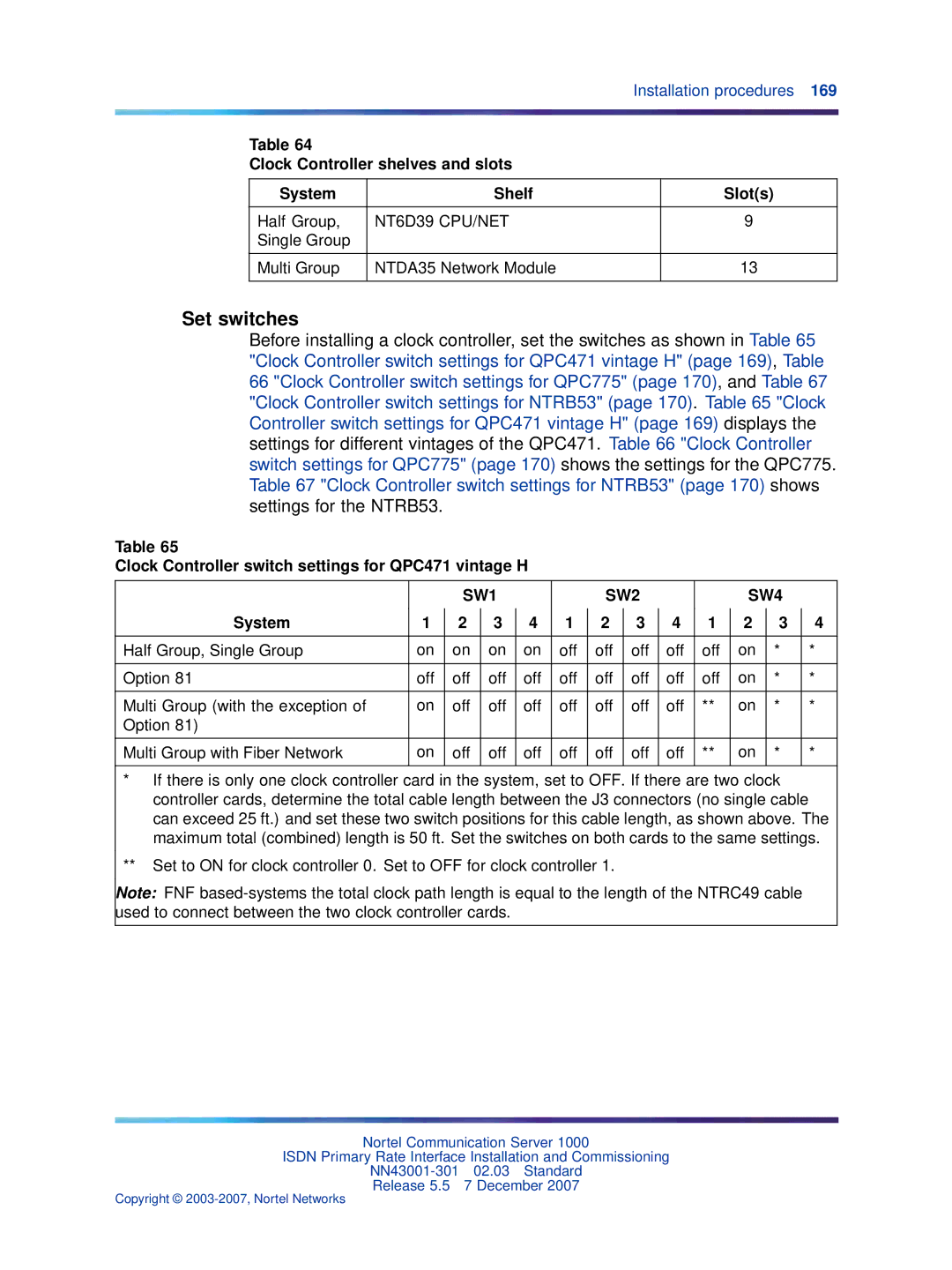
Installation procedures
Determine slots and shelves
Clock Controller switch settings for QPC471 vintage H
Set switches
Clock Controller shelves and slots System Shelf Slots
Single Group Multi Group NTDA35 Network Module
Clock Controller switch settings for NTRB53
Clock Controller switch settings for QPC775 System
Half Group, Single Group
LD 39 commands with the NTRB53 Clock Controller
Clock Controller commands
Command Description
Start the Clock Controller
Clock Controller description and installation
For primary
Trck PCK
For secondary
Frun
End
Switch cores
Procedure Remove old equipment
DIS CC x Disable system clock controller where x = 0 or
Scpu
ENL CC x Enable clock controller card, where x = 0 or
Procedure Installing new equipment
Rcnt
Ssck
Switch system clock from active to standby
Reset alarm counters of all digital cards
Swck
Shared mode
ISL installation
Dedicated mode
ISL configurations
Dchi switch settings
Msdl switch settings
MSDL/ISL settings
Shared mode
ISL in shared mode
Dedicated mode using leased line
ISL dedicated mode, using leased line
Install a modem for ISL applications
Dedicated mode using dialup modem
ISL dedicated mode using dialup Hayes Smartmodem
Telephone numbers
Stored profile
Z0=ATDT7414011 Z1= Z2= Z3=
ISL dedicated mode, using dialup Hayes Smartmodem
Dedicated mode using PRI/DTI trunks
Z0= Z1= Z2= Z3=
ISL dedicated mode using PRI/DTI trunk
QMT11 switch settings
QMT21C switch settings
QMT8 switch settings
Install ISL in dedicated mode digital and analog
ISL installation
Install ISL in shared mode
Procedure Install ISL in dedicated mode
USR = SHA
Echo canceller operating parameters
Echo canceller installation
Echo canceller initialization procedures
Electromagnetic Interference
PRI to Echo canceller pin assignments
PRI to echo canceller cabling
Echo canceller installation
Overview
Mb PRI implementation
Hardware requirements
Circuit cards
Hardware description
Channel Service Units CSU
Cables
Media Gateway/Media Gateway Expansion
Shelf slot assignments
NTRB21 Tmdi card
Logical
Card Slot
NTRB21 Tmdi card faceplate
NTAK09 DTI/PRI circuit card
NTAK09 DTI/PRI circuit card
NTAK20 Clock Controller CC daughterboard
Clocking modes
Clock controller LED states
Shelf slot assignment
Clock controller LEDs
Clock controller
NTAK93 D-channel Handler Interface Dchi daughterboard
Shelf slot assignments for NTRB21, NTAK09 and NTAK20
Install/remove daughterboard on the NTRB21 Tmdi card
Install PRI hardware
Procedure Mounting the NTAK20 daughterboard on the NTRB21
NTBK51BA Downloadable D-channel Ddch daughterboard
Insert/remove the NTRB21 Tmdi card
NTAK20 daughterboard installation on the NTRB21
PRT CFN in LD
Procedure Inserting the NTRB21 Tmdi card
Procedure Removing the NTRB21 Tmdi card
Install/remove daughterboards on the NTAK09 DTI/PRI card
Procedure Mounting the daughterboards on the NTAK09
Procedure Removing the daughterboards from the NTAK09
Daughterboard installation on the NTAK09
Set switches on NTAK09 DTI/PRI card
NTAK09 switch settings Distance to digital Cross connect
LEN
Procedure Installing the NTAK09
Installing the NTAK09
Procedure Connecting the cables
Pin Transmit tip to Network Transmit ring to
Procedure Enabling the NTRB21 Tmdi card
Fgnd
Frame ground
Procedure Enabling the NTAK09 DTI/PRI card
LD 17 Adding a PRI card Prompt Response Description
Procedure Implementing basic PRI
Ctyp Dchi
Type Adan
Cdno
Port
LD 15 Defining a PRI customer Prompt Response Description
Prompt Response Description
Isdn YES
Mode PRA
PNI
Hnpa NPA
Chty BCH
LD 14 Defining service channels and PRI trunks
Ctyp
Inac YES
Type PRI
Rtmb
Feat Syti
CCO
218 1.5 Mb PRI implementation
DTI hardware Description
Mb DTI implementation
DTI/PRI Tmdi card
Set the switches
Install DTI hardware
NTBK04
Connect the cables
NTAK09 switch settings Distance to digital Crossconnect
Pin Transmit tip to network Transmit ring to Network
Procedure Enabling the NTAK09 card
Software enable the DTI/PRI cards
Enll C
Procedure Implementing DTI
Is ESF Must match the far end
LD 17 Adding a DTI card Prompt Response Description
LD 73 Assigning a clock reference source
LD 14 Configuring the trunks Prompt Response Description
226 1.5 Mb DTI implementation
Mb ISL implementation
ISL in dedicated mode using leased line
Using dialup modems
Leased line requirements Hardware Comments
NTAK02
ISL in dedicated mode using dialup modem
ISL hardware installation dedicated mode
Dial-up modem requirements Hardware Comments
NT8D09 Set line card
NTAK02 switch setting Port
Procedure Installing ISL hardware
SDI DCH OFF Dpnss Esdi
Unit J10
End
Procedure Implementing dedicated mode
Implement dedicated mode
Basic ISL implementation
Dchl
IFC SL1
RLS
Clok
LD 15 Enabling Isdn option Prompt Response Description
Rout
Mode Isld
Tktp TIE
Dtrk YES/NO
Chid
Implement shared mode
USR SHA
Islm
237
Mb DTI cabling
NTAK10 2.0 Mb DTI card
Switch S2 Carrier impedance configuration
Switch S1 Clock Controller CC configuration
Switch S1 Off Up On Down
Switch S2 Off Up On Down
Switch S4 Carrier shield grounding
Switch S3 Mode of operation
Switch S3 Off Up On Down
Switch S4 Off Up On Down
DTI software implementation
NTBK05DA pinouts Color Signal
NTBK05DA pinouts
NTBK05CA pinouts
Task summary list
LD 73 Defining the 2.0 Mb DTI Abcd signaling bit tables
LD 17 Adding a 2.0 Mb DTI card Prompt Response Description
Incoming/Outgoing Calls
Sezdr
Sezr
Sezvr
Callr
Cass
Bursr
Clrbs
Rctls
Outgoing Calls
LD 73 Defining the 2.0 Mb DTI pad tables
Tnls YES no
Pdca
ONP
OPX
XUT
ATO
XEM
Code Value dB
Mb DTI pads Code Value dB
Szni YES no
Mfao YES no
MFF CRC
AFF
BPV
LD 73 Defining the grade of service timers for the DTI card
FAP
SLP
LD 73 Defining the 2.0 Mb DTI system timers
CHG Type RDB
Ccgd
Digital TIE trunk routes
Analog TIE trunk routes
LD 14 Defining the associated list of service trunks
CDP
Ncos
BARS/NFCR
Nars
NTBK51 Ddch
Mb PRI hardware requirement Circuit card Description
Ddch
Mb PRI cards
NTBK50 2.0 Mb PRI circuit card
NTAK79 2.0 Mb PRI circuit card
260 2.0 Mb PRI implementation
NTBK51 Downloadable D-Channel Ddch daughterboard
Install the NTAK79 PRI card
NTAK79 with switch locations
Set the switches on the NTAK79
Inspect the NTAK79 circuit card
Switch SW2 Carrier impedance configuration
Switch SW1 Dchi configuration
Switch SW3 Clock controller configuration
Switch SW4 Carrier shield grounding
Insert the NTAK79
Switch SW4 Down On Up Off
Rx-FGND Rx-OPEN Tx-FGND Tx-OPEN
NTAK79 cabling
NTBK05DA pinouts From Pin MDF Connector Color Signal
From Pin MDF Transmit coax Receive coax Connector
Install the NTBK50 PRI card
Procedure Inspecting the NTBK50 circuit card
Switch SW1 Dchi configuration NTAK93 only
Set the switches on the NTBK50
NTBK50 with switch locations
753/4 1203/4 Down On Up Off
Mount the daughterboards on the NTBK50
Step Action
Remove the daughterboards from the NTBK50
Daughterboard installation
NTBK50 cabling
Insert the NTBK50
Task summary
PRI software implementation
Change data
PRI2 digital card number, where xx = 1-9 Option 11C main
Cabinet, 11-19 IP expansion cabinet 1, 21-29 IP expansion
Cabinet 2, 31-39 IP expansion cabinet 3, 41-49 IP expansion
Ctyp Msdl
LDN Xxxx
Rcap MSL
Mode PRI
LD 16 Defining a PRI service route
Dgpt PRI2
Type PRI2
LD 73 Defining system timers and clock controller parameters
MFF AFF CRC
LD 73 Defining PRI parameters and thresholds
Alrm REG ALT
MNG1
Rats
NCG1
OSG1
LD 73 Changing trunk pad category values
Clrs
Feat Pads Pdca
Dset
Pad values Code Value
TYPE=PRI2
Code Value
282 2.0 Mb PRI implementation
ISL hardware requirements
ISL in dedicated mode using leased line
ISL in shared mode
ISL in dedicated mode using dialup modem
Procedure Installing the NTAK02
ISL hardware installation
NTAK02 jumper settings Jumper Strap for Unit Location
NTAK02 switch settings Port SW1-1 SW1-2
Procedure Setting up the D-channel
Port SW1-3 SW1-4
ISL software implementation
LD 17 Shared mode Prompt Response Description
LD 16 Interface type Prompt Response Description
LD 14 Channel identifier Prompt Response Description
Configuring basic ISL capability Step Action
Lapd YES,NO
Part of setup message for calling line identification
LD 15 Enable the Isdn option Prompt Response Description
1000E
Message as Clid
LD 14 Assign a channel identifier
LD 16 Enable the ISL option Prompt Response Description
127 Range for Meridian 1 Small System, Media Gateway 1000B
294 2.0 Mb ISL implementation
Nonstandard cables
Frame Ground
NT8D7206, NT8D7207
QCAD128 wire list From Signal
NT8D7206, NT8D7207 wire list From Color Pack end End Signal
Ground
QCAD129 wire list Echo
From Signal
PRI Signal From
GND
NT8D7205
QCAD133 wire list Color From PRI signal
QCAD328 wire list From Signal
From Color Pack end End Signal
NT8D75 Clock Controller to Clock Controller cable
NT8D74 Clock Controller to InterGroup cable
NT8D79 PRI/DTI to Clock Controller cable
NT8D83 PRI/DTI to I/O cable
NT8D86 Network to I/O cable
NT8D85 Network to IPE cable
NT8D97AX PRI/DTI I/O to MDF cable
NTND26 PRI to Msdl cables
NT9J93AD PRI/DTI Echo Canceller to I/O cable
NTND27 Msdl to I/O panel cables
NTND98 PRI to I/O panel cables
Nonstandard cables
Page
Isdn Primary Rate Interface Installation and Commissioning