Differential pressure
Sitrans P Accessories
Product overview
Transmitters for gage, absolute
Overview
Product overview
Sitrans P measuring instruments for pressure
Series for gage pressure
Mode of operation
Transmitters for gage, absolute and differential pressure
Schematics
Technical specifications
Dimensional drawings
Series for gage and absolute pressure
Rated operating conditions
Power supply UH
Accuracy
������
For absolute pressure
With metal measuring cell
Mbar g psi g1
Up to Bar psi g1
Explosion protection
Output signal
Measuring range
Measuring ranges for absolute pressure only for US market
E10
Sealing material between sensor and housing
Process connection
C11
Sitrans P250 differential pressure transmitter Application
Sitrans P250 for differential pressure
Technische Daten
Certificates and approvals Approval
Conditions of use
Connection 1 +UB
Male thread G1/8-a = CuZn nickel-plated
Width across Flats
Mm inch Inch mm
Female thread G1/8 Stainless steel 1.4305/AISI
Available ex stock Siemens FI 01 ·
Accuracy ≤ 1 %, wetted parts ceramic/stainless steel
Sealing material
Functions
ZD series for gage and absolute pressure
Displays and controls
Power supply
Type a
Selection and Ordering data Order Code
Series for gage and absolute pressure
Input variable
Measured range Span
Overview Application
Sitrans P Compact For gage and absolute pressure
Transmitters for food, pharmaceuticals and biotechnology
Diaphragm seal With aseptic connection
Diaphragm seal With quick-release clamp
Filling liquid
Sitrans P Compact pressure trans
Integral cooling element K01
Measured range Overload pressure
Measured range Overload pres Sure
Hygiene version P01
Clamp-on seal With aseptic connection
ISO pipes to ISO
Measured range
Sitrans P Compact, connection diagram Siemens FI 01 ·
Dimensional drawings Housing
Sitrans P, dimensions in mm inch
Absolute pressure
Sitrans P300 for gage and absolute pressure
Gage pressure
Level
Electronics
Function diagram of electronics
Design Function Device comprises
Operation of the electronics with Hart communication
Tion Electronics
Mode of operation of the measuring cells
Operation of the electronics with Profibus PA communica
Measuring cell for absolute pressure, function chart
Measuring cell for gage pressure, function chart
Parameters Input keys Hart com Munication
Physical variable Physical dimensions
Parameterization of Sitrans P300
Fieldbus interface
Parameters Input keys Profibus PA
Absolute pressure input
Sitrans P300 for gage pressure and absolute pressure
Profibus PA and Foundation Fieldbus
Gage pressure input
With front-flush diaphragm
≤ 0,1% ≤ 0,2% 10 r ≤
≤ 0,2% ≤ 0,4% 30 r ≤ ≤ 0.005 ⋅ r + 0.05%
≤ 0.2 ⋅ r + ≤ 0.25%/10 K ≤ 0.5% 140 .. F
Design version with front-flush dia Phragm
+150 C
Design standard version
Transmitters for food, pharmaceuticals and biotechnology
Communication Foundation Fieldbus
Hart communication
Profibus PA communication
Measuring cell filling
Selection and Ordering data Order No
20 mA/HART
Foundation Fieldbus FF
Stainless steel, deep-drawn and electrolytically Polished
Foundation Fieldbus FF F 8 1 2
Seal diaphragm Measuring cell Stainless steel
See Further designs
Cable socket for M12 plug
Temperature decoupler up to 200 C7 P00
Temperature decoupler up to 250 C P10
Mounting bracket A02
Q64
Setting of pressure indication in pressure Y21 Units
Preset bus address Y25
Q63
Sitrans P300, with oval flange, dimensions in mm inch
Sitrans P300, front-flush, dimensions in mm inch
NuG and pharmaceutical connections
Flanges to EN and Asme
Aseptic flange with notch to DIN 11864-2 Form a
Thread connection G¾, G1 and G2 to DIN
Tank connection TG52/50 und TG52/150
IDF socket with union nut
Sitrans P, DS III series
Transmitters for gage pressure for the paper industry
Device front view, Sitrans P DS
Transmitters for gage pressure for the paper industry
Function
Parameterization
Measuring cell for gage pressure with front-flush diaphragm
Lmp, gallon, bushel, barrel, barrel
Pressure setting can also be
Adjustable parameters Input keys Profibus PA
Temperature F, R Miscellaneous Siemens FI 01 ·
Profibus PA or Foundation Fieldbus
Output signal 20 mA
Signal
DS III series with PMC connection
To EN 61326 and Namur NE Munity
Transmitters for gage pressure for the paper industry
Analog input Adaptation to customer-specif
Electrical connection / cable inlet
Series DS III Hart Measuring cell filling Cleaning
Measuring cell filling Cleaning
Nominal measuring range
P02
M12 cable sockets metal A50 Rating plate inscription
B11
C11 Bration to IEC Acceptance test certificate C12
26.3 mm Approx 33.1 mm
PMC Style standard
40.9 mm Approx 36.8 mm
PMC Style minibolt
To EN 61326 and Namur NE Siemens FI 01 ·
Sitrans P300 with PMC connection
Transmitters for gage pressure for the paper industry
Perature Simulation function Available
Reset function due to metering
Hart communication 230 .. Ω Protocol
Bytes
Y22 + Sure units Y01
40.4 mm Approx 36.8 mm
DS III, DS III PA and DS III FF series Technical description
Front view
Pressure transmitter for gage pressure
Function diagram of the electronics
Measuring cell for gage pressure
Measuring cell for gage pressure, function diagram
Measuring cell for level, function diagram
G/min, g/s, lb/d, lb/h, lb/min, lb/s
Parameterization DS
Parameters Input keys Hart com
MmH2O, ftH2O 20 C, inHg, mmHg
Temperature F, R Miscellaneous Siemens FI 01 ·
DS III series For gage pressure
Sitrans P, DS III series for gage pressure
T4...T6 CL II, DIV 2, GP FG CL Siemens FI 01 ·
Classification according to pressure equip
Internal preprocessing Device profile
EEx ia + EEx d6 Ex nA/nL zone
Display Without indicator
Silicone oil Standard Inert liquid1 Grease-free
Bar g 15 .. .5 psi g Psi g 102.0 ...10153 psi g
Screwed gland M20x1.5 Screwed gland ½-14 NPT Plug M12 metal6
EEx ia + EEx d5 Ex nA/nL zone
Setting of pressure indication Y22 + Non-pressure units Y01
Digital indicator alongside the input keys D27
Explosion-proof Intrinsic safety to E25 Inmetro Brazil
Explosion-proof Intrinsic safety to E55 Nepsi China
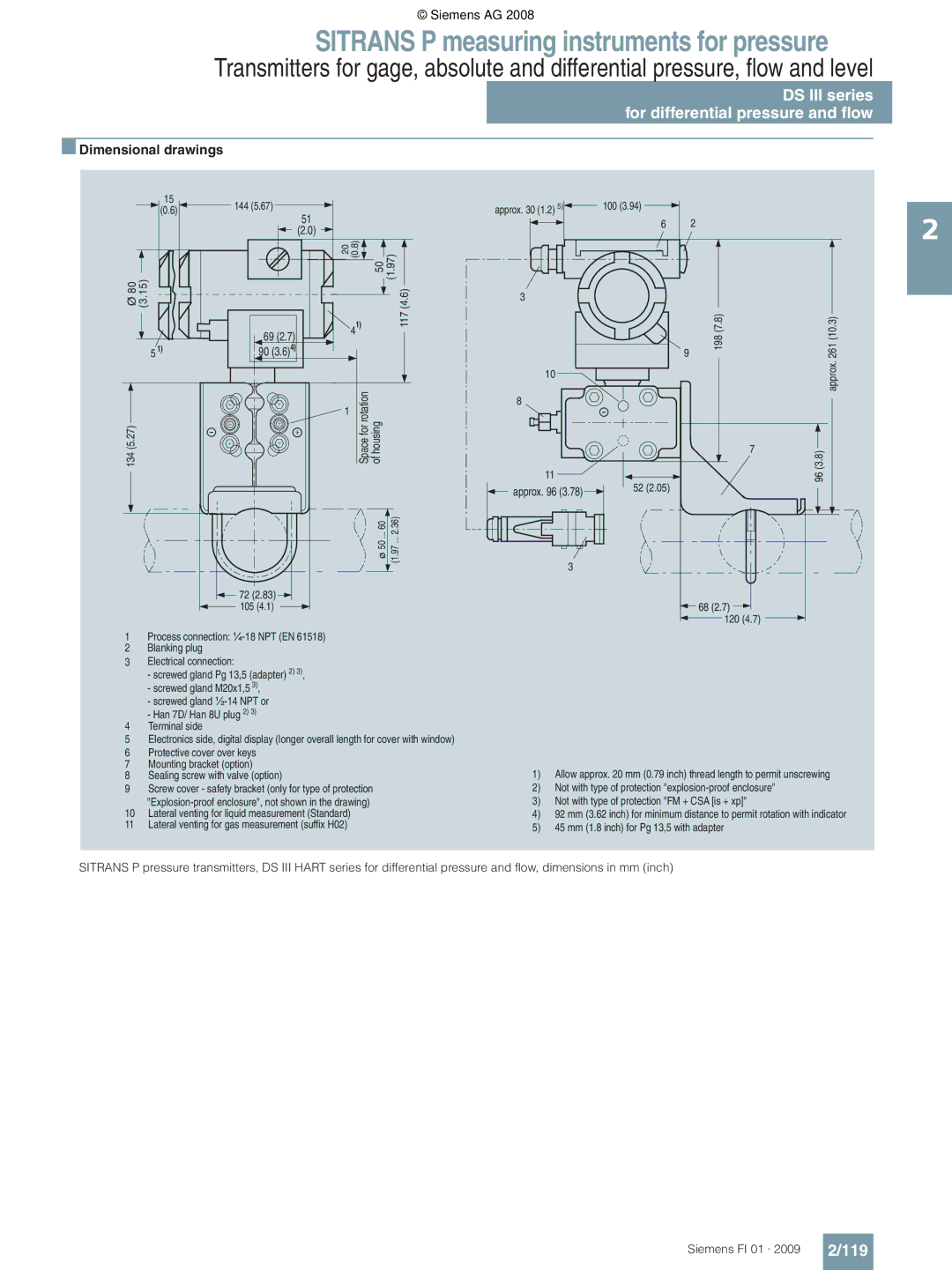
Dimensional drawings
Sitrans P measuring instruments for pressure
Input absolute pressure, with front-flush Diaphragm
40 ... +200 C -40 ... +392 F
Weight without options ≈ 1.5 kg ≈ 3.3 lb Housing material
10 ... +85 C 14 ... +185 F
40 ... +150 C -40 ... +302 F
Ehedg
Hart communication
Bar g1 Psi g1 Mbar a2 Psi a2 Bar a2
Absolute pressure, front-flush membrane
Seal diaphragm Connection shank Stainless steel
Flange version with Order code M.., N.., R.. or
M49 Threaded connection acc. to DIN Form a
Temperature decoupler up to 200 C4 P00
PROFIsafe certificate and protocol C21 Flanges to EN
M48
Additional data
300 255 mm Siemens FI 01 ·
115 mm Approx 100 140 mm 52 mm 150 mm 170 mm 165 mm 200 mm
Asme B16.5 Varivent connection
IDF threaded socket
Tank connection TG52/50 and TG52/150
133 100 159
Aseptic threaded socket to DIN 11864-1 Form a
95 x 1/6 110 x ¼ 100 130 x ¼
113
Profibus PA or Foundation Fieldbus Input
Profibus PA or Foundation Fieldbus
Profibus PA or Foundation Fieldbus Certificate and approvals
Hart communication
Pressure, from the pressure series DS III Hart
Mbar a Psi a Bar a
Hidden, setting mA With visible digital indicator
E55 China
C11 Bration to IEC 60770-2 Acceptance test certificate2 C12
Dimensional drawings
Sitrans P measuring instruments for pressure
Technical specifications
Design
100
101
EEx ia + EEx d Ex nA/nL zone
102
Pressure, from the differential pressure
Casting6
Casting
103
104
Sealing screw with valve option
105
106
464 psi InH 2O Mbar 160 bar
DS III series for differential pressure and flow
107
Wetted parts materials Seal diaphragm
Weight without options ≈ 4.5 kg ≈ 9.9 lb Housing material
108
109
Profibus PA or Foundation Fieldbus Power supply UH
Graph 3 sound engineering practice PN 420 MWP 6092 psi
110
111
PN 32 MWP 464 psi Mbar2 4015 .. .03 inH2O
PN 32/160 MWP 464/2320 psi Measuring cell filling Cleaning
112
Tial pressure and flow, Series DS III Hart
Wetted parts materials stainless steel process flanges
Zone 2 planned Intrinsic safety, explosion-proof enclosure
113
PN 32 MWP 464 psi Mbar2 03 inH2O
114
Y221 Non-pressure units
Setting of pressure indicator in pressure Y21 Units
115
Y02
PN 420 MWP 6092 psi Display
116
Silicone oil Standard
117
Y22 + Non-pressure units Y01 or
118
Explosion-proof Zone 2 to Nepsi China E57
Max digits Y02 Up to Mbar, bar, kPa, MPa, psi
119
120
121
Process connection ¼-18 NPT EN 61 Blanking plug
122
123
Sitrans P, DS III series for level
DS III series for level
124
Yes Siemens FI 01 ·
125
To EN 61326 and Namur NE Nity
Classification according to pressure equipment
126
Mounting flange
127
Process connection of low-pressure side
128
Use on zone 1D / 2D E01
129
Rings for process flanges on Low-pressure side
A31 Sealing screws
Tube length
130
Y221 Non-pressure units + Y01
Mounting flange F 4 9 1
= available
131
Flame flashover lock-out A01
Tation
200 138 160 150 or 220 115 158 180 235 162 190
132
Nom. diam Nom. press
200 138 721 160 150 or 220 115 158 180 235 162 190
133
Structural design
Sitrans P Accessories
Supplementary electronics for 4-wire connection
134
E86060-K6017
Supplementary electronics for 4-wire Connection
135
Output current
136
Vent on side for gas measurements H02 Process flanges
137
A23 Acceptance test certificate C12
Process connection G½A D16 Remote seal flanges D20
Without process flanges K00
Replacement measuring cell for level F 4 9 9
138
Rated measuring range
139
140
141
Selection and Ordering data
142
Valve manifolds mounted on Sitrans P DS
143
144
Valve manifolds mounted on Sitrans P300
145
Integration
Transmitters for hydrostatic level
MPS series submersible sensor
146
Cable hanger Application
147
Junction box Application
148
7MF1570-5ZA02-Z
149
More information
Quick-release diaphragm seal
Remote seals for transmitters and pressure gages
150
Designs
Miniature diaphragm seal with diaphragm flush with front
Temperature error
151
Transmission response
Recommendations
152
Response time
290 870 6000 Phragm seal G1½B 058 145 2000
Technical specifications Temperature error Diaphragm seals
153
Inch Mbar Psi 10 K 10 K ⋅ m Kap
Inch Mbar Psi 10 K
154
155
Temperature error Clamp-on seals
Maximum temperature of medium
Calculation of the temperature error
Example of temperature error calculation
Dependence of temperature error on diaphragm material
Response times
Technical data of filling liquids
Filling liquid Density Temperature
157
Diaphragm seals of sandwich design
Diaphragm seals of sandwich design
158
159
Connection to Asme B16.5
160
Connection to EN
Diaphragm seals of flange design with flexible capillary
Diaphragm seals of flange design
161
Length of capillary4
162
To a pressure transmitter Sitrans P order separately
163
4404/316L B16.5 RF 125 .. AA For the other materials
164
165
Nom Diam Press
166
Pressure transmitter
167
Diaphragm seal Mounting flange with tube as option for
168
Mounting flange with tube as option for
Flanged remote seal without tube, fitted by
Nom. Nom Diam. press
169
200 138 160 DN 100 PN 158 180 235 162 190
Quick-release diaphragm seal
Quick-release diaphragm seals
For gage, absolute and differential pressure
170
Vacuum-proof design V03
171
Connection to pressure transmitter
Connection to transmitter
172
0 15 ³ R
Vacuum-proof design V01
Miniature diaphragm seal
173
Miniature diaphragm seals
Process connection
Flushing rings
For diaphragm seals
174
Connection to Asme B
175
Clamp-on seals for flange-mounting
Clamp-on seals of flange design
For gage pressure, differential pressure and flow
176
Delivery 1 off
177
Class
178
179
Remote seals Weight Approx kg approx .82 lb
Quick-release clamp-on seals
For pressure and absolute pressure
Pressure 7MF403 7 and 7MF423 7 together with Order
180
For Sitrans P pressure transmitters for
Clamp connection for pipes to BS 4825/3 and o.D. tubes
181
Connection to DIN 11851 with screw necks
182
Measuring setups
Remote seals
183
Measuring setups with remote seals
184
Types of installation for level measurements closed vessels
185
Measuring setups without remote seals
186
Measuring setups for closed containers
187
Y01
188
Values must be entered here Siemens FI 01 ·
189
Range
Material acceptance test certificate to EN
Fittings
190
New standard DIN EN
Selection of available shut-off valves
Selection aid
191
212 Tion DN 5/DN 8 for vapor Measurement 7MF9416-6
192
Differential pressure transmit
201 Way valve manifolds 206
193
Shut-off valves to DIN 16270, DIN 16271 and DIN
194
Characteristic curves
Shut-off valve, form B, dimension drawing, dimensions in mm
Angle adapters 7MF9401-7WA
Overview Dimensional drawings
Angle adapter
195
196
Double shut-off valves
197
Accessories for shut-off valves / double shut-off valves
198
Way valve manifolds DN
199
200
Connection diagram of the 2-way valve manifolds
201
5-spindle valve manifolds DN
202
203
Spindle valve manifold DN 5 7MF9411-5B., dimensions in mm
204
Multiway cocks PN
Multiway cock in oil-free and grease-free design
Accessories Dimensional drawings
Accessory set for multiway cock PN
205
For non-aggressive liquids For aggressive Gases Liquids
Way and 5-way valve manifolds DN
206
Overview Function
207
BB C
208
209
Component Material Mat. No Housing P250GH 0460 4571
Way valve manifold DN
For wall mounting or for securing on rack 72 mm grid
Accessory set for 3-way valve manifold DN 8 for flanging
For pipe mounting, weight 0.7 kg M12 7MF9006-6GA
210
211
Dimensional drawings Schematics
Valve manifold DN Blow-out valves DN
Valve manifold combination DN 5/DN
212
Valve manifold combination DN 5/DN 8 for Vapors
213
Valve manifold Blow-out valves
Valve manifold combination DN
214
Without test connection With test connection M20 ×
215
Functions
216
Mounting clips 2 off
217
218
Spindle valve manifold DN 5, connections Siemens FI 01 ·
219
Spindle valve manifold DN 5, connections
M18 7MF9006-6PA Required for mounting on 2 stand
220
Valve manifolds for vertical differential Pressure lines
Mounting bracket Required for wall mounting or for
Mounting bracket for mounting on 2 standpipe
Accessory set connection between manifold and transmitter
221
222
223
Accessory set for low-pressure multiway cock
Low-pressure multiway cock
224
OptionsCharacteristic curves
Mounting bracket 7MF9004-6AA M13, dimensions in mm
225
Fittings Accessories
Oval flange
226
Adapters, connection glands
227
Connection parts G 1/2
Made
Water traps, Sealing rings to EN
228
M56340-A54
Pressure surge reducers
229
Pressure surge reducer
230
Shut-off valve 7MF9017-1A., dimensions in mm
Shut-off valve 7MF9017-1B. and -2B., dimensions in mm
Primary shut-off valves
Shut-off valve for aggressive liquids and gases
231
X b 7MF9017
Shut-off valve for non-aggressive liquids, gases and vapors
232
Compensation vessel 7MF9015-1.., dimensions in mm
Compensation vessel 7MF9015-5.., dimensions in mm
Compensation vessels
233
Connection parts
234