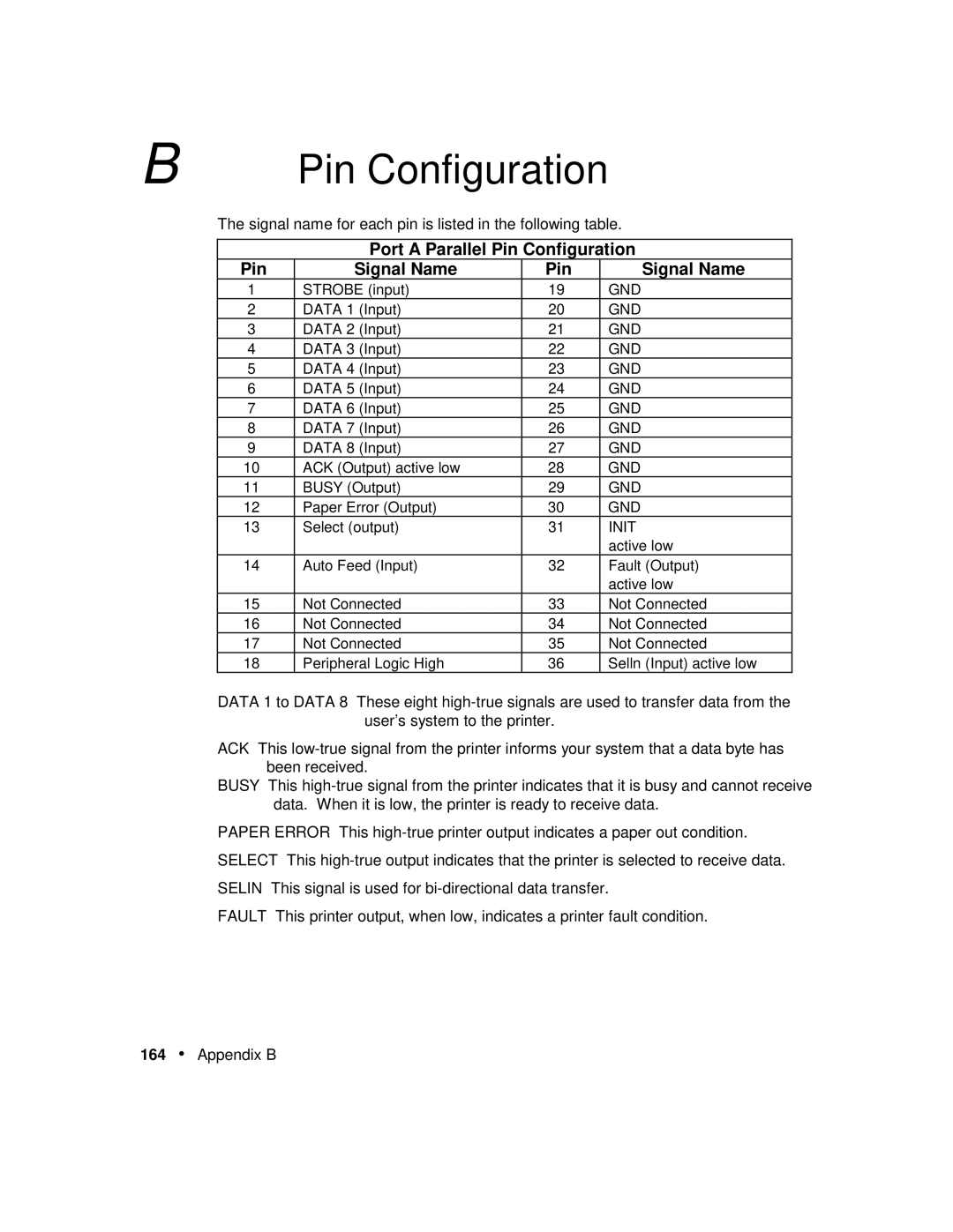
B | Pin Configuration | |||
| The signal name for each pin is listed in the following table. | |||
|
|
|
|
|
|
| Port A Parallel Pin Configuration | ||
| Pin | Signal Name | Pin | Signal Name |
| 1 | STROBE (input) | 19 | GND |
| 2 | DATA 1 (Input) | 20 | GND |
| 3 | DATA 2 (Input) | 21 | GND |
| 4 | DATA 3 (Input) | 22 | GND |
| 5 | DATA 4 (Input) | 23 | GND |
| 6 | DATA 5 (Input) | 24 | GND |
| 7 | DATA 6 (Input) | 25 | GND |
| 8 | DATA 7 (Input) | 26 | GND |
| 9 | DATA 8 (Input) | 27 | GND |
| 10 | ACK (Output) active low | 28 | GND |
| 11 | BUSY (Output) | 29 | GND |
| 12 | Paper Error (Output) | 30 | GND |
| 13 | Select (output) | 31 | INIT |
|
|
|
| active low |
| 14 | Auto Feed (Input) | 32 | Fault (Output) |
|
|
|
| active low |
| 15 | Not Connected | 33 | Not Connected |
| 16 | Not Connected | 34 | Not Connected |
| 17 | Not Connected | 35 | Not Connected |
| 18 | Peripheral Logic High | 36 | Selln (Input) active low |
DATA 1 to DATA 8 These eight
ACK This
BUSY This
PAPER ERROR This
FAULT This printer output, when low, indicates a printer fault condition.
164• Appendix B
