April 14, 2006 | Appendix B: Specifications |
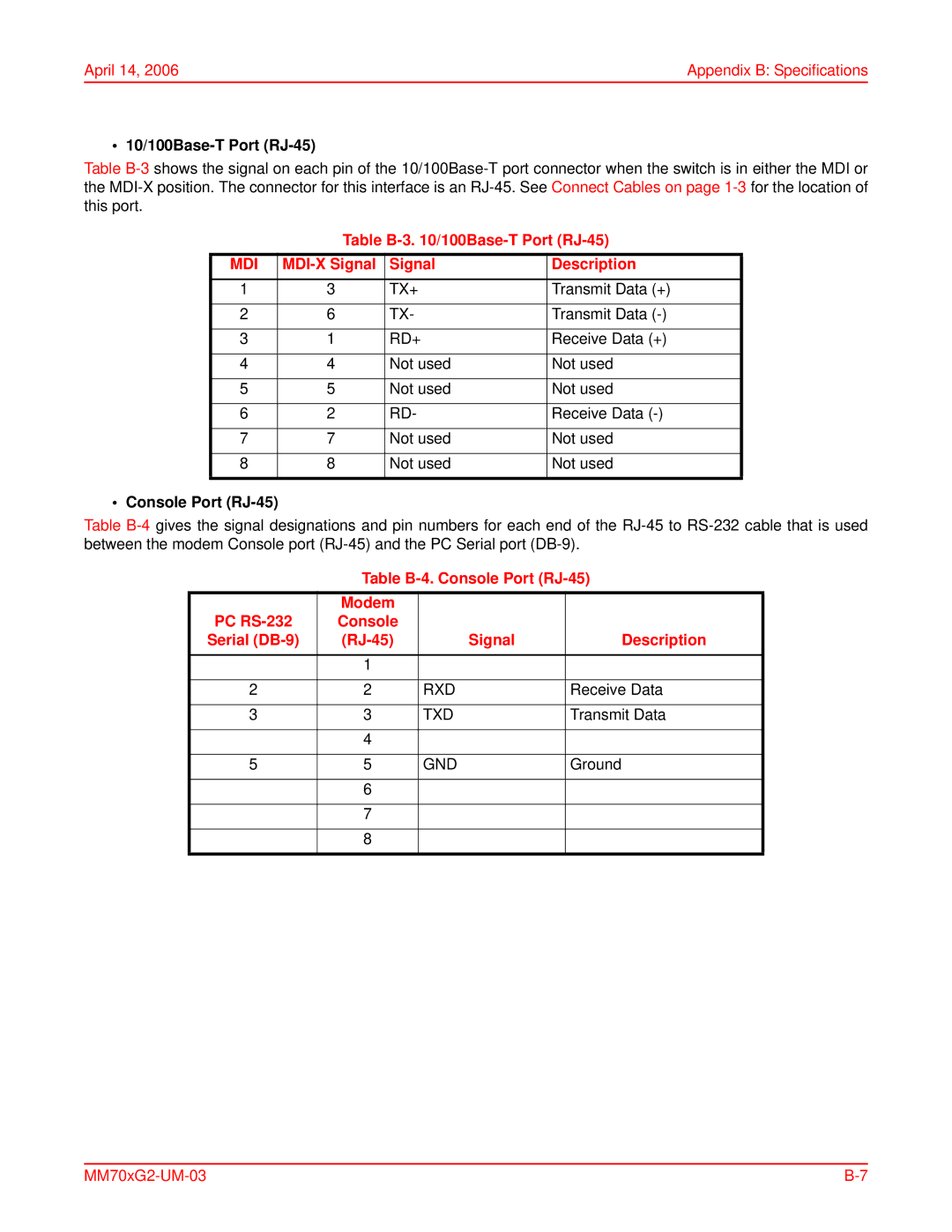
• 10/100Base-T Port (RJ-45)
Table
Table B-3. 10/100Base-T Port (RJ-45)
MDI | Signal | Description | |
1 | 3 | TX+ | Transmit Data (+) |
|
|
|
|
2 | 6 | TX- | Transmit Data |
|
|
|
|
3 | 1 | RD+ | Receive Data (+) |
|
|
|
|
4 | 4 | Not used | Not used |
|
|
|
|
5 | 5 | Not used | Not used |
|
|
|
|
6 | 2 | RD- | Receive Data |
|
|
|
|
7 | 7 | Not used | Not used |
|
|
|
|
8 | 8 | Not used | Not used |
|
|
|
|
• Console Port (RJ-45)
Table
Table B-4. Console Port (RJ-45)
| Modem |
|
|
PC | Console |
|
|
Serial |
| Signal | Description |
|
|
|
|
| 1 |
|
|
|
|
|
|
2 | 2 | RXD | Receive Data |
|
|
|
|
3 | 3 | TXD | Transmit Data |
|
|
|
|
| 4 |
|
|
|
|
|
|
5 | 5 | GND | Ground |
|
|
|
|
| 6 |
|
|
|
|
|
|
| 7 |
|
|
|
|
|
|
| 8 |
|
|
|
|
|
|