Chapter 1: Installation | April 14, 2006 |
Step |
| Action |
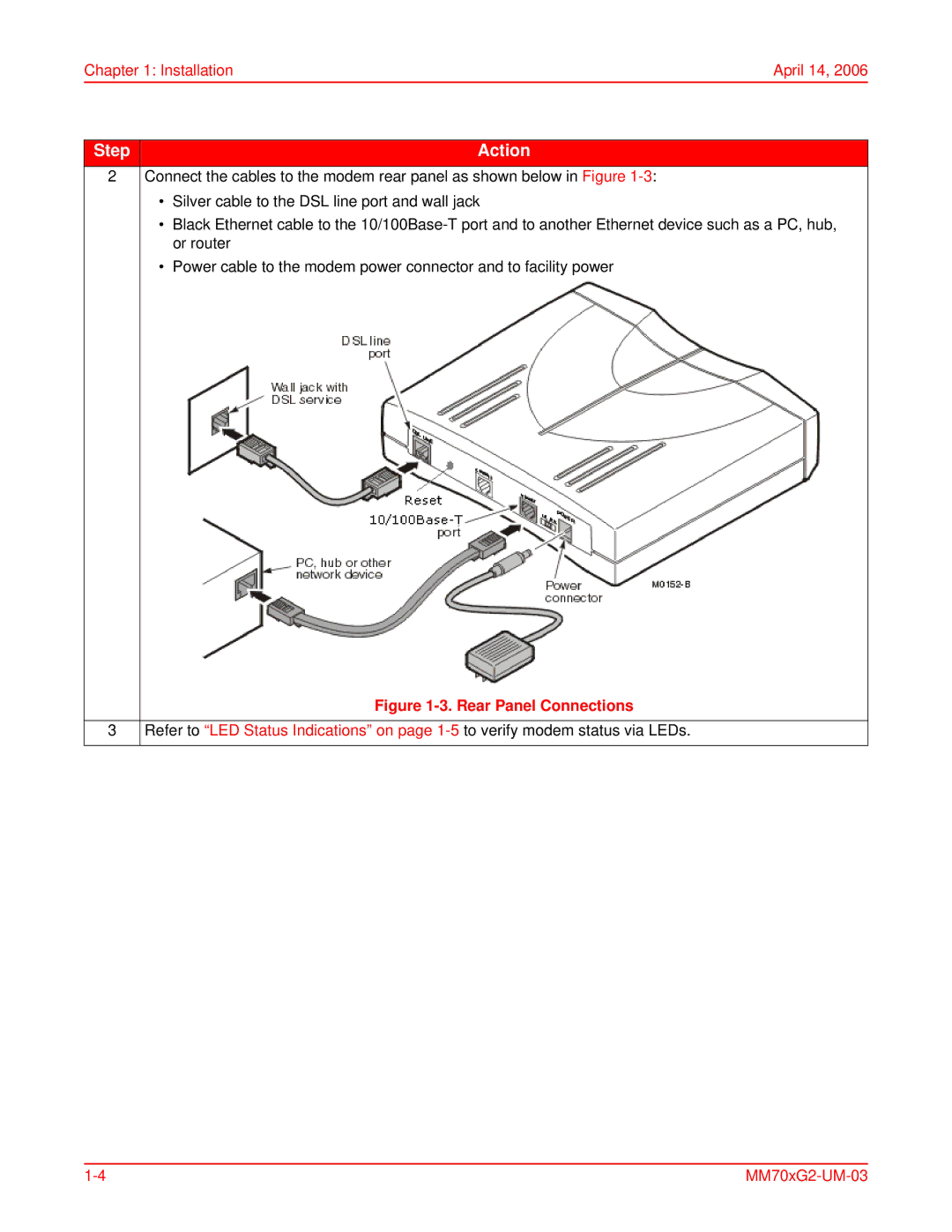
2 | Connect the cables to the modem rear panel as shown below in Figure | |
| • | Silver cable to the DSL line port and wall jack |
| • | Black Ethernet cable to the |
|
| or router |
| • | Power cable to the modem power connector and to facility power |
|
| Figure |
|
| |
3 | Refer to “LED Status Indications” on page | |
|
|
|