Agilent Technologies 1664A Logic Analyzer
Agilent Technologies 1664A Logic Analyzer
Agilent Technologies 1664A Logic Analyzer
This Book
Table of Contents
Contents
To adjust the CRT intensity
To test the time interval accuracy
Self-Tests Description
Gpib Optional RS-232COptional Centronix
Viii
General Information
Accessories
Accessories Supplied Part Number Qty
Accessories Available
Accessories Available Part Number
Specifications
Supplemental Characteristics
Probes
State Analysis
Timing Analysis
Indicators
Measurement and Display Functions
Measurement Functions
Data Entry/Display
Auxiliary Power
Dimensions
Marker Functions
Operating Environment
Product Regulations
EMC
Recommended Test Equipment
Recommended Test Equipment
Equipment Required
Preparing for Use
Check the supplied accessories
To inspect the logic analyzer
Inspect the shipping container for damage
Inspect the product for physical damage
Ferrites
Ferrites
To apply power
To apply power
To operate the user interface
To set the line voltage
To clean the logic analyzer
To degauss the display
To test the logic analyzer
To degauss the display
Page
Testing Performance
Testing Performance
To perform the self-tests
Select the Front Panel Test
To perform the self-tests
Select the Display Test
To make the test connectors
Materials Required
To make the test connectors
Set up the equipment
To test the threshold accuracy
Connect the logic analyzer
Set up the logic analyzer
To test the threshold accuracy
Test the TTL threshold
To test the threshold accuracy
Test the ECL threshold
Test the − User threshold
Test the + User threshold
Test the 0 V User threshold
Test the next pod
Pulse Generator Setup
Set up the pulse generator
To test the glitch capture
Oscilloscope Setup
Set up the oscilloscope
To test the glitch capture
Connect the Logic Analyzer to the Pulse Generator
Test the glitch capture on the connected channels
Set up the Waveform menu to view all the channels
Test the next channels
To test the single-clock, single-edge, state acquisition
To test the single-clock, single-edge, state acquisition
Set up the Format menu
Set up the Trigger menu
Connect the 1664A Logic Analyzer to the Pulse Generator
Verify the test signal
To test the single-clock, single-edge, state acquisition
Select the logic analyzer setup/hold time
Check the setup/hold combination
Setup/Hold Combinations
Select the clock to be tested
Clocks
To test the single-clock, single-edge, state acquisition
Select the clock to be tested
Test the next setup/hold combination
To test the multiple-clock, multiple-edge, state acquisition
To test the multiple-clock, multiple-edge, state acquisition
Set up the Format menu
Pod 1, channel
Verify the test signal
To test the multiple-clock, multiple-edge, state acquisition
0.0 ns 4.5 ns 2.5 ns
Select the clocks to be tested
To test the multiple-clock, multiple-edge, state acquisition
Select the clocks to be tested
Hen continue through the complete test
Set up the pulse generator according to the following table
To test the single-clock, multiple-edge, state acquisition
To test the single-clock, multiple-edge, state acquisition
Set up the Format menu
Channel
Verify the test signal
To test the single-clock, multiple-edge, state acquisition
These procedures
Logic analyzer Format menu, select Master Clock
Oscilloscope Timebase Delay
Test the next clock
To test the time interval accuracy
EXT Trig
Function Generator Setup
To test the time interval accuracy
Set up the Format menu
Set up the Waveform menu. a Press the Waveform key
Acquire the data
Performance Test Record
Performance Test Record 1664A Logic Analyzer
Performance Test Record
Calibrating and Adjusting
Calibrating and Adjusting
Logic analyzer calibration
To adjust the CRT monitor alignment
Cause personal injury
To adjust the CRT monitor alignment
Enter the Sys PV tests, then enter the Display Test
To adjust the CRT intensity
Press the front panel Select key
To adjust the CRT intensity
Troubleshooting
Troubleshooting
To use the flowcharts
Troubleshooting
To use the flowcharts
Troubleshooting
Troubleshooting
Troubleshooting
To use the flowcharts
To use the flowcharts
Troubleshooting
Troubleshooting
Troubleshooting
Troubleshooting
Troubleshooting
Troubleshooting
To check the power-up tests
To check the power-up tests
As the tests complete, check if they pass or fail
Select the Chip 5 Tests menu and press the Select key
To run the self-tests
To run the self-tests
To run the self-tests
To run the self-tests
Select the Front Panel Test
To run the self-tests
To test the power supply voltages
To test the power supply voltages
Load the +5.00 V supply with a 2 Ω, 25 watt resistor
Loaded by the acquisition board
Signals on the Power Supply Cable
To test the CRT monitor signals
To test the CRT monitor signals
CRT Monitor Cable Signals
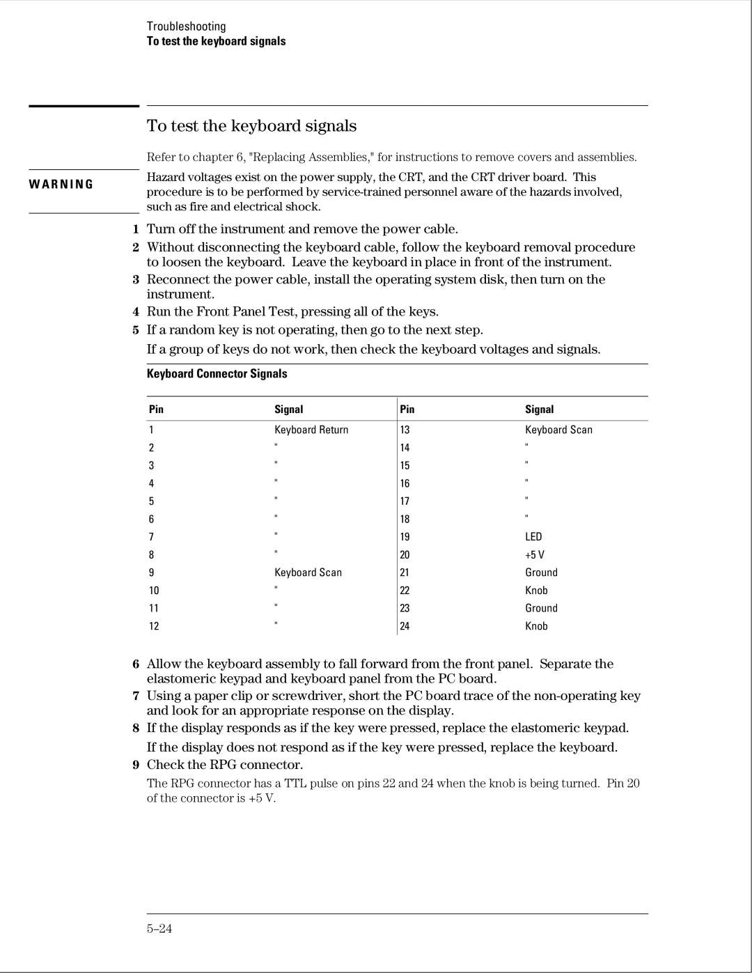
To test the keyboard signals
Turn off the instrument and remove the power cable
To test the keyboard signals
Keyboard Connector Signals
To test the disk drive voltages
To test the disk drive voltages
Pin Signal Description
Disk Drive Voltages
To perform the BNC test
Press the Config key Assign pods 1 and 2 to Machine
To perform the BNC test
To test the logic analyzer probe cables
Set up the logic analyzer Configuration menu
To test the logic analyzer probe cables
Set up the Format menu. a Press the Format key
Select Clear Trigger, then select All
Return to the troubleshooting flowchart
To test the auxiliary power
To test the auxiliary power
Replacing Assemblies
Replacing Assemblies
Exploded View
Listing
Replacing Assemblies
Reverse this procedure to install the cover
To remove and replace the handle
To remove and replace the feet and tilt stand
To remove and replace the cover
Using previous procedures, remove the following assemblies
Reverse this procedure to install the disk drive
To remove and replace the disk drive
To remove and replace the disk drive
To remove and replace the power supply
To remove and replace the power supply
To remove and replace the Main Circuit board
Verify the push-on, push-off action of the assembly
To remove and replace the switch actuator assembly
To remove and replace the switch actuator assembly
To remove and replace the rear panel assembly
To remove and replace the rear panel assembly
To remove and replace the front panel and keyboard
To remove and replace the intensity adjustment
To remove and replace the front panel and keyboard
Reverse this procedure to install the handle plate
To remove and replace the monitor
To remove and replace the handle plate
To remove and replace the monitor
To remove and replace the line filter
To remove and replace the fan
To remove and replace the fan
To remove and replace the optional Gpib and RS-232C cables
Remove accessories from the logic analyzer
To return assemblies
Package the logic analyzer
Seal the shipping container securely, and mark it Fragile
Replaceable Parts
Parts listed
Replaceable Parts Ordering
Parts not listed
Direct mail order system
Exploded View
Exploded View
Replaceable Parts List
Replaceable Parts List
Replaceable Parts List 1664A Replaceable Parts
Agilent Des Part Qty Description Number
MP1
RS-232 loopback connector
Power Cables and Plug Configurations
Power Cables and Plug Configurations
Theory of Operation
Theory of Operation
Block-Level Theory
1664A Logic Analyzer
1664A Theory
System Memory
CRT Controller and Display RAM
Disk Drive Controller
CRT Monitor Assembly
Power Supply
External Keyboard Interface
Centronix Interface
Theory of Operation
Logic Acquisition Circuitry
Comparators
Main Circuit Board Logic Acquisition Theory Probing
Acquisition
Threshold
Test and Clock Synchronization Circuit
Self-Tests Description
Power-up Self-Tests
ROM Test
System Tests System PV
System Tests System PV
RAM Test
Interrupt Test
Gpib Test
RS-232C Test
HIL Test
Disk Test
Front Panel Test
Perform Test All
Display Test
Analyzer Tests Analy PV
Analyzer Tests Analy PV
Board Test
Chip Tests
Data Input Inspection
Gpib Optional
RS-232C Signal Definitions
RS-232COptional
Centronix Signal Definitions
Centronix
Page
Declaration of Conformity
Page
Document Warranty
Product Warranty