1Getting Started Tutorial
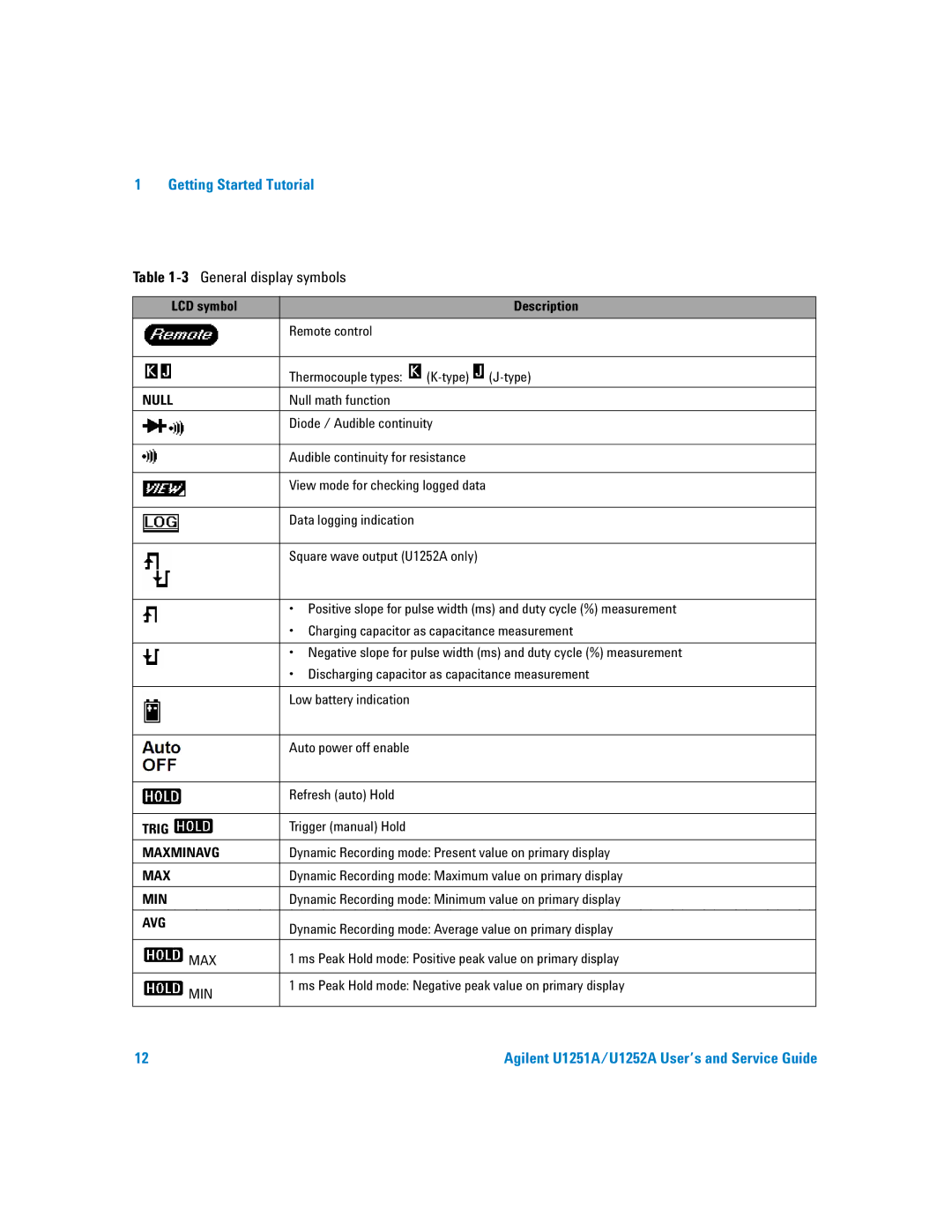
Table 1-3 General display symbols
|
| LCD symbol |
| Description | ||
|
|
|
|
| Remote control |
|
|
|
|
|
|
|
|
|
|
|
|
| Thermocouple types: | |
|
|
|
|
| ||
|
|
|
|
| ||
|
|
|
|
|
|
|
NULL | Null math function |
| ||||
|
|
|
|
|
| |
|
|
|
|
| Diode / Audible continuity | |
|
|
|
|
| ||
|
|
|
|
|
| |
|
|
|
|
|
|
|
|
|
|
|
| Audible continuity for resistance | |
|
|
|
|
|
| |
|
|
|
|
| View mode for checking logged data | |
|
|
|
|
|
|
|
|
|
|
|
| Data logging indication |
|
|
|
|
|
|
| |
|
|
|
|
| Square wave output (U1252A only) | |
|
|
|
|
|
| |
|
|
|
|
| • Positive slope for pulse width (ms) and duty cycle (%) measurement | |
|
|
|
|
| • Charging capacitor as capacitance measurement | |
|
|
|
|
|
| |
|
|
|
|
| • Negative slope for pulse width (ms) and duty cycle (%) measurement | |
|
|
|
|
| • Discharging capacitor as capacitance measurement | |
|
|
|
|
|
|
|
|
|
|
|
| Low battery indication |
|
|
|
|
|
|
|
|
|
|
|
|
| Auto power off enable |
|
|
|
|
|
|
|
|
|
|
|
|
| Refresh (auto) Hold |
|
|
|
|
|
|
|
|
TRIG | Trigger (manual) Hold |
| ||||
|
|
|
|
|
| |
MAXMINAVG | Dynamic Recording mode: Present value on primary display | |||||
|
|
|
|
|
| |
MAX | Dynamic Recording mode: Maximum value on primary display | |||||
|
|
|
|
|
| |
MIN | Dynamic Recording mode: Minimum value on primary display | |||||
|
|
|
|
|
|
|
AVG | Dynamic Recording mode: Average value on primary display | |||||
|
|
|
|
| ||
|
|
|
|
|
| |
|
|
|
| MAX | 1 ms Peak Hold mode: Positive peak value on primary display | |
|
|
|
|
|
| |
|
|
|
| MIN | 1 ms Peak Hold mode: Negative peak value on primary display | |
|
|
|
|
|
| |
|
|
|
|
|
|
|
12 | Agilent U1251A/U1252A User’s and Service Guide |
